10
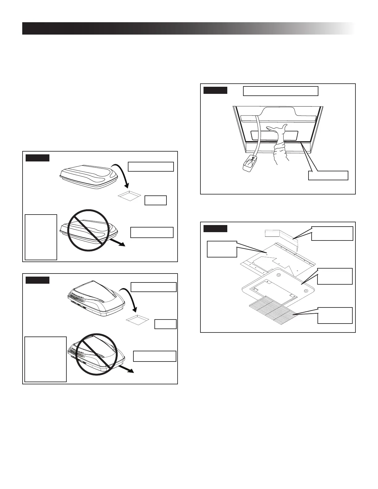
H. Installing Unit
1. Check gasket alignment of the unit over the
roof opening and adjust if necessary. Unit may
be moved from below by slightly lifting. See
(FIG. 14).
FIG. 14
Roof Gasket
Center Unit From Below
2. Remove return air cover and ceiling template
from carton. See (FIG. 15).
FIG. 15
Divider Plate
Return Air
Cover
Ceiling
Template
Return Air
Grille
3. All models listed in this manual will use a four
(4) bolt pattern for installing the RAG kit. These
bolts along with the Romex connector and junc-
tion box cover are furnished in part number
3107180.006 (bolt kit) and is purchased sepa-
rately.
4. Reach up into the return air opening and pull the
unit electric cord down. Mount the junction box
with screws to the framing in front of the roof
opening. See (FIG. 16).
INSTALLATION INSTRUCTIONS
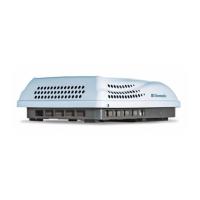
G. Placing Unit On Roof
1. Remove the unit from the carton and discard
carton.
2. LIFTING HAZARD. Use proper
lifting technique and control when lifting product.
Failure to obey this caution could result in injury.
Place unit on roof.
3. Do NOT slide unit. Otherwise,
damage to gasket (on bottom of unit) may occur,
and could cause a leak.
Lift and place the unit over the prepared open-
ing using the gasket on the unit as a guide. See
(FIG. 12) & (FIG. 13).
FIG. 12
Do Not Slide
Lift And Place
Front
Model
641815
641816
641835
651815
651816
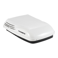
FIG. 13
Do Not Slide
Lift And Place
Front
Model
641815C & H
641816C & H
641835C & H
651815C & H
651816C & H
4. Place the electronic control box kit and the RAG
kit inside the RV. These boxes contain mounting
hardware for the unit and will be used inside the
RV.
This completes the outside work. Minor
adjustments can be done from inside the
RV if required.