9
INSTALLATION INSTRUCTIONS
3. Optional Indoor Temperature Sensor
a. Refer to the instructions provided with the
indoor temperature sensor for details of in-
stallation.
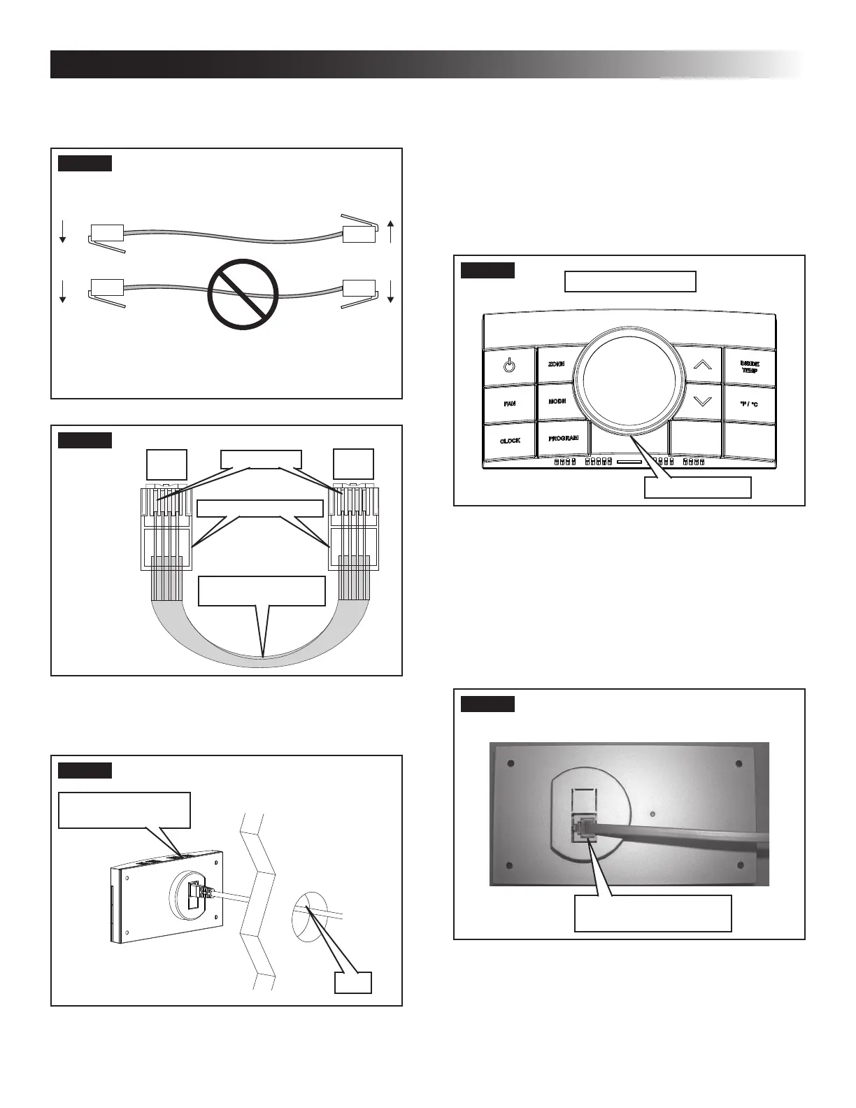
4. Thermostat Installation
a. Carefully separate the thermostat base plate
from the thermostat cover. Insert a small
screw driver into the slot on bottom of ther-
mostat and disengage the tab. See (FIG. 10).
FIG. 10
Disengage Tab
CCC 2 Thermostat
b. Insert the 4 conductor communication cable
through the hole in base plate. Align thermo-
stat base plate with hole in wall. Make sure
base plate is level and attach base plate to
wall using the four (4) supplied screws.
c. Insert the 4 conductor communication cable
connector (RJ-116C4P) into the connector
on the back of the thermostat. See (FIG. 11).
FIG. 11
4 Conductor
Communication Cable
d. Align the thermostat with the back plate and
snap into position.
RJ-11-6C4P connectors MUST be in-
stalled as shown in (FIG. 7) & (FIG. 8).
FIG. 7
FIG. 8
RJ-11-6C4P Connector
Pin 1
Black
Red
Green
Yellow
Black
Red
Green
Yellow
Flat Four Conductor
Communication Cable
2. Route the communication cable through the 2″
diameter hole in the wall required for the ther-
mostat. See (FIG. 9).
FIG. 9
CCC 2 Thermostat
(Rear View)
Wall