6
B. Roof Preparation
1. FIRE OR ELECTRICAL SHOCK
HAZARD. Make sure there are no obstacles
(wires, pipes, etc.) inside RV’s [roof / oor /
walls]. Shut OFF gas supply, disconnect 120
Vac power from RV, and disconnect positive (+)
12 Vdc terminal from supply battery BEFORE
drilling or cutting into RV. Failure to obey these
warnings could result in death or serious injury.
Opening Requirements - Before preparing
the ceiling opening, the type of system op-
tions MUST be decided upon. Read all of
the following instructions before beginning
the installation.
2. Carefully mark and cut the required roof opening.
See “B. Roof Requirements” on page (4).
3. Using the roof opening as a guide, cut the match-
ing hole in the ceiling.
4. Maintain structural integrity. Oth-
erwise damage to product and/or RV could oc-
cur.
5. NEVER create a low spot on RV
roof. Otherwise, water will pool and could cause
a leak.
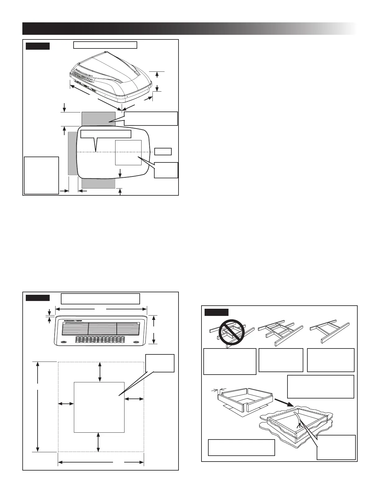
The opening created must be framed to provide
adequate support and prevent air from being
drawn from the roof cavity. Framing stock 3/4″
or more in thickness must be used. Remember
to provide an entrance hole for power supplies,
indoor temperature sensor (if applicable), ther-
mostat communication cable, and furnace wires
(if applicable) at the front of the opening. See
(FIG. 4).
3/4″ Min.
Do Not Cut Roof
Structure Or
Rafters
Good-Rafters
Supported By
Cross Beams
Good Location
Between Roof
Rafters
Frame Opening So It
Won't Collapse When
Bolting Down Unit
FIG. 4
15″ Min. At
Front Of
Opening
Leave Access For
Power Supply Wiring
INSTALLATION INSTRUCTIONS
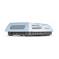
FIG. 2
Dimensions Are Nominal
10-3/8″
29″
40-1/2″
Keep These Areas
Free Of Obstructions
Front
Center Line Of Unit
Model
641815C & H
641816C & H
641835C & H
651815C & H
651816C & H
Roof
Opening
12″
4″
4″
b. Maintain structural integrity.
Otherwise damage to product and/or RV
could occur.
The roof must be designed to support 130
pounds when RV is in motion. Normally a
200 lb. static load design will meet this re-
quirement.
c. Check inside the RV for return air grille (here-
inafter referred to as “RAG”) obstructions
(i.e. door openings, room dividers, curtains,
ceiling xtures, etc). See (FIG. 3).
FIG. 3
Dimensions Are Nominal
3/4″
17″
17″
17″
1-1/4″
1-1/2″
1-1/2″
17″
1-3/4″
Roof
Opening