14
2. System Checkout
a. Verify that all features of the installed sys-
tem work. See CCC 2 thermostat Operating
Instructions or User’s Guide. Check the fan
mode, cooling mode, heat pump mode (if
applicable), and furnace mode (if applicable)
operation. If the features do not work discon-
nect the 120 Vac and 12 Vdc power supplies
and verify that all wiring is correct and that
the correct dip switches have been set to the
“ON” position.
M. Furnace /Aqua Temperature Dierential
Setting
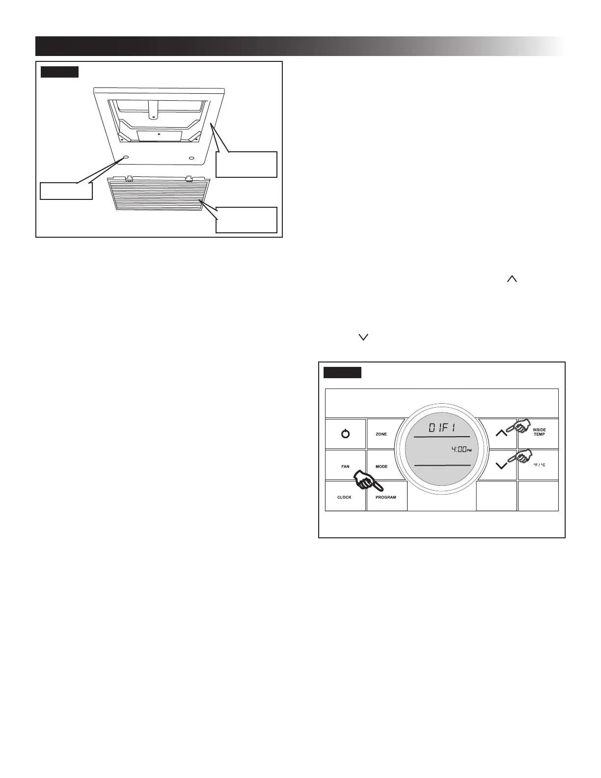
This system can be congured to operate using an ON/OFF
dierential of either 1 degree F or 2 degree F. See (FIG. 25).
1. To set the dierential, simultaneously press
the PROGRAM button and the up button
on the CCC 2 thermostat. “diF1” will appear in
the display while the buttons are pressed. See
(FIG. 25). To set the 2 degree dierential, simul-
taneously press the PROGRAM button and the
down button. “diF2” will appear in the display
while the buttons are pressed.
FIG. 25
FIG. 24
Return Air
Cover
Hole Plug
Return Air
Grille
L. System Reset & Checkout
1. System Reset
After setting the dip switches in the electronic
control, do a system reset.
a. Re-connect the 12 Vdc and 120 Vac power
supplies.
b. Make sure the CCC 2 thermostat is in the
OFF mode.
c. Simultaneously press the MODE and Zone
buttons. The LCD will display “Init” and all
available zones.
d. Release the MODE and Zone buttons.
e. Press the ON/OFF button to exit system set
up.
f. When a dip switch is turned on after initial
configuration, a system reset will need to be
done before the CCC 2 thermostat will rec-
ognize the updated selection.
INSTALLATION INSTRUCTIONS