10
B. Attach Top Mounting Brackets
1. When awning is in predetermined location,
place top mounting brackets (with arm assem-
bly) directly under and parallel to awning rail.
See (FIG. 1) & (FIG. 13).
To determine correct awning location, see
subsection, “D. Determine Awning Loca-
tion” on page (7).
The motorized arm assembly is ALWAYS
installed at the RH side of awning.
Some awning rails have a wide drip chan-
nel to catch water as it runs off RV roof. If
awning rail is too wide, it may be neces-
sary to lower the position of top mounting
brackets to avoid interference with FRTA.
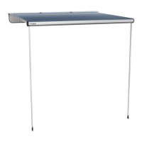
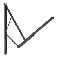
FIG. 13
Awning Rail
Top Mounting Brackets
FRTA
Arm Assemblies
2. While holding arm assemblies securely in place,
mark top mounting hole locations (LH and RH
top mounting bracket slots). See (FIG. 13).
3. Wiring hole for motorized arm assembly. See
(FIG. 1).
The motorized arm assembly is ALWAYS
installed at the RH side of awning.
Wiring harness location is determined by
awning model. The back channel will ei-
ther have a notch at top, or a hole near
bottom for wiring to pass through RV wall.
a. If wiring will pass through RV wall at BOT-
TOM of back channel, skip to step (4).
b. If wiring will pass through RV wall at TOP of
back channel, mark wiring hole (notch) loca-
tion.
4. Move arm assemblies out of the way.
5. Drill 3/16″ diameter holes through marked
mounting hole locations and into solid structure
of RV.
Drill 7/32″ diameter holes if drilling into
steel.
INSTALL AWNING
6. Drill (1) 5/8″ diameter hole at marked TOP wiring
hole location and through outside wall of RV.
Skip this step if wiring will pass through
RV wall at BOTTOM of RH back channel.
7. With arm assembly completely closed, replace
top mounting brackets against wall and align its
mounting holes to the pre-drilled holes in RV.
8. Control arm assemblies while in-
stalling brackets. When weight of FRTA is NOT
supported, downward force could cause arm as-
semblies to swing sideways and damage RV.
Apply sealant to #14 - 10 x 1-1/2″ hex head
screw threads. Then place and tighten (1) screw
through outside slot of top mounting bracket and
into solid structure of RV. See (FIG. 14).
Make sure arm assemblies are completely
closed before tightening outside screws.
Closed arm assemblies will help in the
overall alignment of awning.
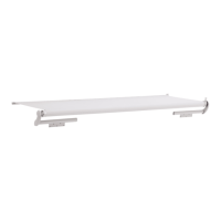
FIG. 14
Awning
Rail
LH Top
Mounting
Bracket
#14 - 10 x 1-1/2″
Hex Head Screw
LH End Cap
9. IMPACT OR PINCH HAZARD.
Arm assemblies are under tension from gas
strut. Hold arm assemblies and FRTA securely
BEFORE removing ties. Otherwise, arms will
extend quickly and unexpectedly. Failure to
obey this warning could result in death or seri-
ous injury.
While holding arm assembly (front channel) and
FRTA securely, carefully remove nylon ties (and
tape if applicable) around front and back chan-
nels. Then allow front channel to open slowly
until awning fabric is taut.
Slack from unfurled fabric will allow aw-
ning to open approximately 12″ - 18″.
10. Apply sealant to #14 - 10 x 1-1/2″ hex head
screw threads. Then place and tighten (1) screw
through inside slot of top mounting bracket and
into solid structure of RV. See (FIG. 15).
 Loading...