4445103618 27
Activating the auxiliary charging output
The auxiliary charging output can be activated for
automatic trickle charging of the starting battery,
e.g. in the event of power consumption during
long idle periods.
I
➤Slide the DIP switch (fig. 2 9, page 3) to the
position shown in the table below activate or
deactivate the auxiliary charging output for the
starting battery.
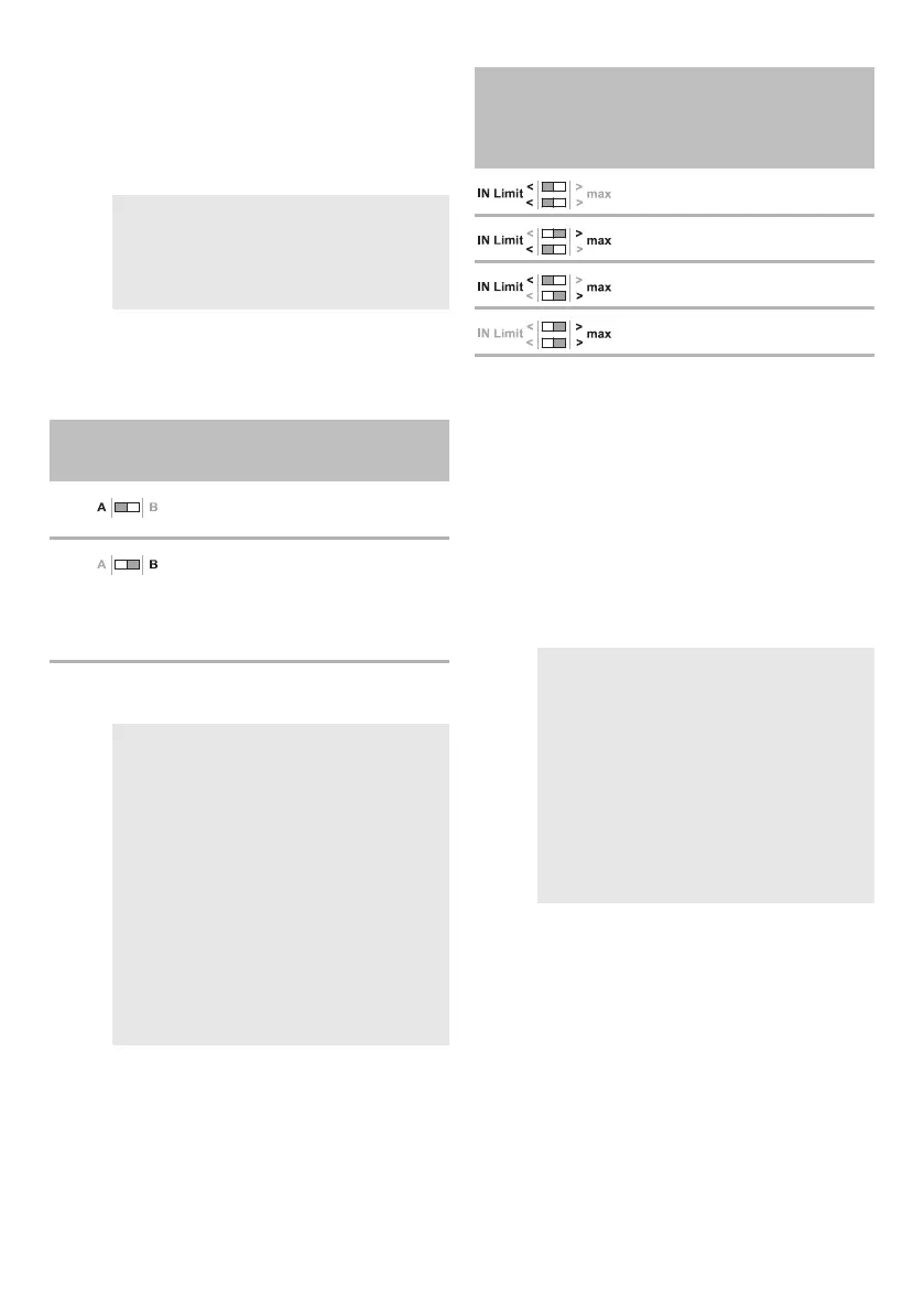
Limiting the current consumption
I
➤Slide the DIP switches (fig. 2 9, page 3) to the
position shown in the table below to reduce the
current consumption from starter circuit or alter-
nator.
Setting the operating mode
Depending on the operating mode set, the
charging booster is activated via the D+ signal or
the voltage at the starting battery.
➤Slide the DIP switches (fig. 2 9, page 3) to the
position shown in the table below to set the
operating mode.
I
• The charging booster starts charging the house
battery as soon as the value for “Increase of
charging power” is reached on the starting bat-
tery. The charging booster continuously
increases the charging power from 3 % of the
charging power until the required (maximum)
charging power is reached.
• If the voltage falls below the “switch-off thresh-
old” value for 30 sec, the charging booster
switches off automatically.
NOTE
Deactivate the auxiliary charging output if an
auxiliary charging output is already present
within the system (e.g. as part of a central elec-
trical system).
DIP switch
position (gray)
Description
The auxiliary charging output is
deactivated.
The auxiliary charging output is
activated. The starting battery is
automatically trickle charged with
0 – 3 A/ 5 A if the house battery is
fully charged.
NOTE
Depending on the charging phase (see
chapter “Battery charging function” on
page 21), the current consumption of the
charging booster from the starter circuit
or the alternator can be higher than the
charging current for the house battery
during driving. Reduce the current con-
sumption:
• To relieve a low-power alternator
• To compensate for under-dimen-
sioned wiring on the vehicle side
between the starting battery and the
central electrical system.
DIP switch
position (gray)
Maximum current
consumption
MT LB 50 MT LB 60 MT LB 90
68 A 82 A 125 A
49 A* 67 A 100 A
42 A* 55 A 82 A
33 A* 43 A 64 A
*Applicable when using existing cables and fuses and
depending on the performance of the central electrical
system used.
NOTE
• If the charging booster is activated via
the D+ signal, the starting battery can
be discharged when the ignition is
switched on and the engine is not run-
ning. Use a D+ active simulator if no
D+ signal is available.
• To activate a change of the settings,
disconnect the device temporarily
from the power supply, the starting
battery and the house battery.
 Loading...