26 4445103618
Operation
I
Setting the charging program
A
I
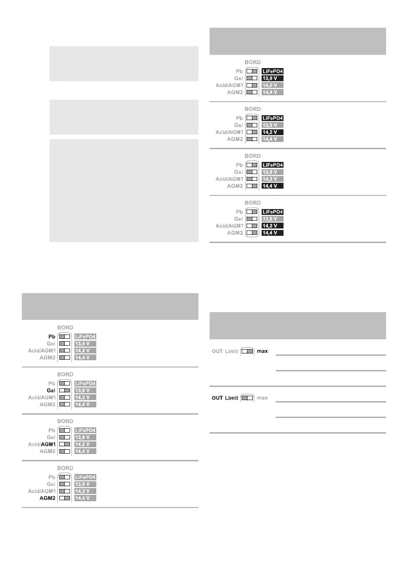
➤Slide the DIP switches (fig. 2 8, page 3) to the
position shown in the table below to set the
charging program for the respective type of
house battery.
Adapting the charging current
➤Slide the DIP switch (fig. 2 9, page 3) to the
position shown in the table below to adapt the
charging current to the capacity of the house
battery.
NOTE
Use a small screwdriver to carefully move
the DIP switches to the required position.
NOTICE! Damage hazard
Only use batteries that are suitable for the
specified charging voltage.
NOTE
• Select the charging program suitable
for the type of house battery used
based on the manufacturer's specifica-
tions, the information in the table
below and the technical data (see
chapter “Technical data” on page 32).
• The specified charging times apply to
an average ambient temperature of
20 °C.
DIP switch position
(gray)
Desired charging
program
Lead-acid batteries (14.4 V)
(fig. 9, page 6)
•U1: 14.4V (2–6h)
•U2: 13.5V
Lead gel batteries (14.4 V)
(fig. 0, page 6
•U1: 14.4V (6–12h)
•U2: 13.8V
AGM batteries (14.4 V)
(fig. a, page 6)
• U1: 14.4 V (1.5 – 5 h)
•U2: 13.5V
AGM batteries (14.7 V)
(fig. c, page 7)
•U1: 14.7V (1.5–5h)
•U2: 13.6V
LiFePO4 batteries (13.9 V)
(fig. d, page 7)
• U1: 13.9 V (0.5 – 1 h)
•U2: 13.9V
LiFePO4 batteries (14.2 V)
(fig. e, page 7)
• U1: 14.2 V (0.5 h)
•U2: 13.6V
LiFePO4 batteries (14.4 V)
(fig. f, page 7)
• U1: 14.4 V (0.3 – 1 h)
•U2: 13.8V
LiFePO4 batteries (14.6 V)
(fig. 6, page 5)
• U1: 14.6 V (0.3 – 0.5 h)
•U2: 13.8V
DIP switch
position (gray)
Charging
current
MT LB 50 0 – 50 A
MT LB 60 0 – 60 A
MT LB 90 0 – 90 A
MT LB 50 0 – 45 A
MT LB 60 0 – 50 A
MT LB 90 0 – 75 A
DIP switch position
(gray)
Desired charging
program
 Loading...