Installation Dometic Interact
10
EN
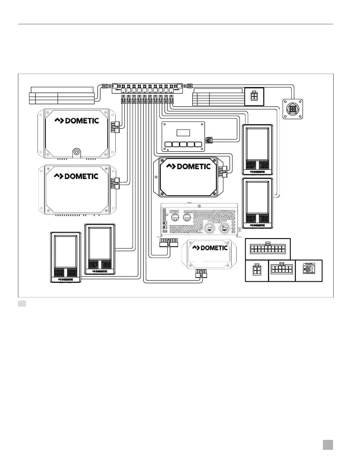
3.2 Installing the Distribution Board
The diagram below shows one possible configuration of
the system components installed on the distribution
board.
12 System Configuration Example
The diagram above shows one possible configuration of
the system components installed on the distribution
board. Connect the RVC devices in any sequence.
Use any length of connection between the distribution
boards, but the length of the twisted pair wires between
a distribution board and a device should be less than 6 ft
(183 cm) in order to gain the proper RVC communication.
1
Pin Designation
12VDC
GROUND
RVC -
RVC +
Communication
GROUND
Distribution Board Plugs
Communication
Input /Out put (Type)
12VDC
4
3
2
GREY
7
4
1
DIAGNOSTIC PLUG
3
6
9
All Connections Are
Wire Si de Vi ew
43
2
1
BATT FRESH BLACK
LPG
120 Ohm
MADE IN CA NADA
GARNET
INSTRUMENTS LTD.
LEVEL IN PERCENT
SEELEVEL II TANK MONITOR
10
All Connections Are
Wir e Side View
6
54
3
21
12 11
9
78
10 2 14635879
12 111416 131518 1720
19
All Connections Are Wire Side View
All Connections Are
Wir e Side View
43
2
1
Xantrex Freedom XC Pro 2000
CIRCUITSCIRCUITS
120 Ohm
2
Pin
1
Input/Output (Type)
Input
Input
FUSED 12VDC FROM DC PANEL
Designat ion
12VDC
GROUND
DC Distribution Board
DB100
S/W Version V1.25
1 2 3 4 5 6 7 8 9 10
12V
Outputs
Outputs
H- Bridge
Driver Board
DB200
S/W Version v1.18
Outputs
Climate Control Module
TM-2021
S/W Version v1.30
Wi-Fi Server Module
LR125
S/W Version v1.10
Outputs
3.5" Display
I
Refer to RVC Communications Network Overview
for more information.
 Loading...