Q3 & Qht Controls for Direct Expansion Systems Operational
L-2516 ENGLISH 23
In addition, since the seawater pump utilizes a magnetically driven impeller, remove the impeller from the wet-end assembly,
wipe with an alcohol solution, and store in a warm, dry area until commissioning takes place.
SPECIFICATIONS
OPERATIONAL
Set Point Operating Range. . . . . . . . . . . . . . . . . . . . . . . . . . . . . . . . 55°F to 99°F (12.8°C to 37.2°C)
Sensor Accuracy . . . . . . . . . . . . . . . . . . . . . . . . . . . . . . . . . . . . . . . .± 2°F @ 77°F (±1.1°C @ 25°C)
Low Voltage Limit 115 Volt Units . . . . . . . . . . . . . . . . . . . . . . . . . . . . . . . . . . . . . . . . . . . . . . .90 VAC
Low Voltage Limit 220 Volt Units . . . . . . . . . . . . . . . . . . . . . . . . . . . . . . . . . . . . . . . . . . . . . .200 VAC
Line Voltage . . . . . . . . . . . . . . . . . . . . . . . . . . . . . . . . . . . . . . . . . . . . . . . . . . . . 95 through 240 VAC
Frequency. . . . . . . . . . . . . . . . . . . . . . . . . . . . . . . . . . . . . . . . . . . . . . . . . . . . . . . . . . . . . 50 or 60 Hz
Fan Output . . . . . . . . . . . . . . . . . . . . . . . . . . . . . . . . . . . . . . . . . . . . . . 6 Amps @ 115 VAC/230 VAC
Valve Output . . . . . . . . . . . . . . . . . . . . . . . . . . . . . . . . . . . . . . . . . . . . . . . . . 5 Amps @ 115/230 VAC
Aux Heater Output (using off-board relay) . . . . . . . . . . . . . . . . . . . . . 30 Amps @ 115 VAC/230 VAC
Pump Output . . . . . . . . . . . . . . . . . . . . . . . . . . . . . . . . . . . 1/4 HP at 115 VAC or 1/2 HP at 230 VAC
Compressor Output . . . . . . . . . . . . . . . . . . . . . . . . . . . . . . . . . . .1 HP @ 115 VAC/2 HP @ 230 VAC
Minimum Operating Temperature . . . . . . . . . . . . . . . . . . . . . . . . . . . . . . . . . . . . . . . . . 0°F (-17.8°C)
Maximum Ambient Operating Temperature . . . . . . . . . . . . . . . . . . . . . . . . . . . . . . . . .180°F (82.2°C)
Maximum RH Conditions . . . . . . . . . . . . . . . . . . . . . . . . . . . . . . . . . . . . . . . . . 99% Non Condensing
Power Consumption . . . . . . . . . . . . . . . . . . . . . . . . . . . . . . . . . . . . . . . . . . . . . . . .Less Than 5 Watts
DIMENSIONS
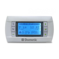
Q3 Display Panel . . . . . . . . . . . . . . . . . . . . . . .3.50” (89mm) W x 2.53" (65mm) H x 0.75” (19mm) D
Qht Display Panel . . . . . . . . . . . . . . . . . . . . . . . . . . . . . . . . . . . . 4.84” (123mm) W x 3.27" (83mm) H
Qht Panel Cut Out . . . . . . . . . . . . . . . . . . . . . . . . . . . . . . . . . 3-7/16" (88mm) W x 2-1/8" (54mm) H
Q3 Panel Cut Out . . . . . . . . . . . . . . . . . . . . . . . . . . . . . . . . . . . . . . . . . . . . . . . 1" (26mm) round hole
CABLE LENGTHS
Display Cable . . . . . . . . . . . . . . . . . . . . . . . . . . . . . . . . . . . . . . . . . . . . . . . . . . . . . .15' (4.6m) Typical
Ambient Air Sensor. . . . . . . . . . . . . . . . . . . . . . . . . . .7' (2.1m) Standard on Self-Contained Systems
Outside Air Sensor (optional) . . . . . . . . . . . . . . . . . . . . . . . . . . . . . . . . . . . . . . 75' (22.9m) Maximum
All custom display-cable lengths supplied in standard 5' (1.5m) increments . . 75' (22.9m) Maximum
SYSTEM INPUTS
Ambient or Inside-Air Temperature . . . . . . . . . . . . . . . . . . . . . . . . . . . . . . . . . . . . . . . . . . . . . . . . . . .1
High Refrigerant Pressure . . . . . . . . . . . . . . . . . . . . . . . . . . . . . . . . . . . . . . . . . . . . . . . . . . . . . . . . . 1
Low Refrigerant Pressure (optional). . . . . . . . . . . . . . . . . . . . . . . . . . . . . . . . . . . . . . . . . . . . . . . . . .1
Outside Air Temperature Sensor (optional) . . . . . . . . . . . . . . . . . . . . . . . . . . . . . . . . . . . . . . . . . . . .1
Seawater Input Temperature Sensor (optional) . . . . . . . . . . . . . . . . . . . . . . . . . . . . . . . . . . . . . . . . .1
Humidity Sensor (optional) . . . . . . . . . . . . . . . . . . . . . . . . . . . . . . . . . . . . . . . . . . . . . . . . . . . . . . . . .1
NOTE
Collect all discharged liquids and recycle or dispose of in a proper manner in accordance with federal, state and/or
local regulations.
NOTE
Maximum length of display and sensor cables is 75 feet (22.9m).