Q3 & Qht Controls for Direct Expansion Systems Important Programming Notes To Installer and End User
L-2516 ENGLISH 5
IMPORTANT PROGRAMMING NOTES TO INSTALLER AND END USER
If your air conditioning unit is Cool Only (does not have a reversing valve), then you MUST set Programmable Function 19 to
“CL” for Cool Only. Once this parameter is set, the only allowable operational modes that can be selected are OFF, COOL, and
DEHUMIDIFICATION. (See Programmable Function “19: Cool-Only Mode” on page 12 for more information.)
NORMAL HEATING OR COOLING CYCLE
In Automatic Mode, heating and cooling are supplied as required. If Cooling is required, the system will start a cooling cycle
when the cabin temperature exceeds the set point by the Compressor Differential setting in Programmable Function 3 (1.5°F/
0.8°C by default) and will continue to cool until the temperature equals the set point. Similarly, if Heating is required, the system
will start a heating cycle when the cabin temperature is below the set point by the Compressor Differential setting and will
continue to heat until the temperature equals the set point.
If you select Cool Mode, only cooling is supplied. If you select Heat or (optional) Aux Heat Mode, only heating is supplied. The
cabin temperature in either mode is maintained within the Compressor Differential setting.
During a Cooling or Heating cycle, the fan will operate at a fan speed depending on the fan’s operational mode. If a Manual fan
speed is selected, the fan will operate at this speed at all times, even if the set point has been satisfied and the cooling or
heating cycle has ended. If the fan is in Auto mode, the fan speed will be determined by Programmable Function 4, the Fan
Response Differential, and Programmable Function 22, Fan-Speed Divisions. Please refer to these parameters for further
details on the fan speeds during Auto fan operation. When in Auto fan mode, the fan speed will return to low speed once the set
point temperature has been satisfied and the cooling or heating cycle has ended.
REVERSING VALVE OPERATION
The position of the reversing valve determines if the system is in Cool Mode or Heat Mode. When the reversing valve is not
energized, the system will operate in Cool Mode. When energized, the system will operate in reverse-cycle heating. In addition,
the reversing valve will toggle (switch back and forth) to relieve the system’s internal refrigerant pressures in these situations:
• Just before the system starts the compressor if the compressor has not run for less than 2 minutes.
• When a cycle is interrupted from the display panel by pressing the POWER button or changing the set point.
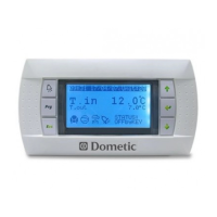
INSTALLING THE DISPLAY PANEL
MOUNTING THE DISPLAY
1. For the Qht display, make a rectangular cut-out in the panel where it will be mounted. The Qht cut-out size is 3-7/16”
(88mm) wide by 2-1/8” (54mm) high. For the Q3 display, only a 1” (26mm) round hole is required in the panel for
mounting.
2. Use the installation instructions included with your display to complete the mounting, securing the display with the
appropriate size and number of screws.
3. Plug one end of the display cable (6-pin connector) to the back of the display and the other end to socket labeled
“Display” located on the edge of the circuit board.
MOUNTING THE SENSORS
AMBIENT TEMPERATURE SENSOR - REQUIRED
Install the ambient temperature sensor in a proper location to accurately sense the room air temperature. Ideally, the sensor
should be located in a reliable return-air stream moving from the room to be controlled to the air conditioner it is plugged into.
Locating the sensor on the back of the air conditioner coil is not ideal and can result in false readings for several reasons. It is
best to locate the sensor just inside of a return-air grille or passage. The standard cable length for the remote air sensor is 7 feet
(2.1m). Plug in the sensor’s 6-pin connector to the “Inside Temp” socket located on the edge of the circuit board.
SEAWATER TEMPERATURE SENSOR - OPTIONAL
Install the optional seawater temperature sensor to monitor the temperature of the seawater feeding the air conditioner. Ensure
that the sensor is in direct contact with the copper pipe and use thermal mastic to ensure good heat transfer. Strap the sensor
wire in place for strain relief and to prevent the sensor from being accidentally removed. Plug the sensor’s 2-pin connector into
the “Loop Water Out” (blue) socket located in the corner of the circuit board.
NOTE
Do not staple any sensor cables when mounting.