HIGH VOLTAGE CABLE
Disconnect high voltage cable from electrode. If sparking starts during trial-for-ianition, the cable is
good. If there is no sparking during trial-for-ianition
'
disconnect high voltage cable at the igniter. If
there is a sparking sound from the igniter during trial-for-ianition, then replace high voltage cable.
ELECTRODE
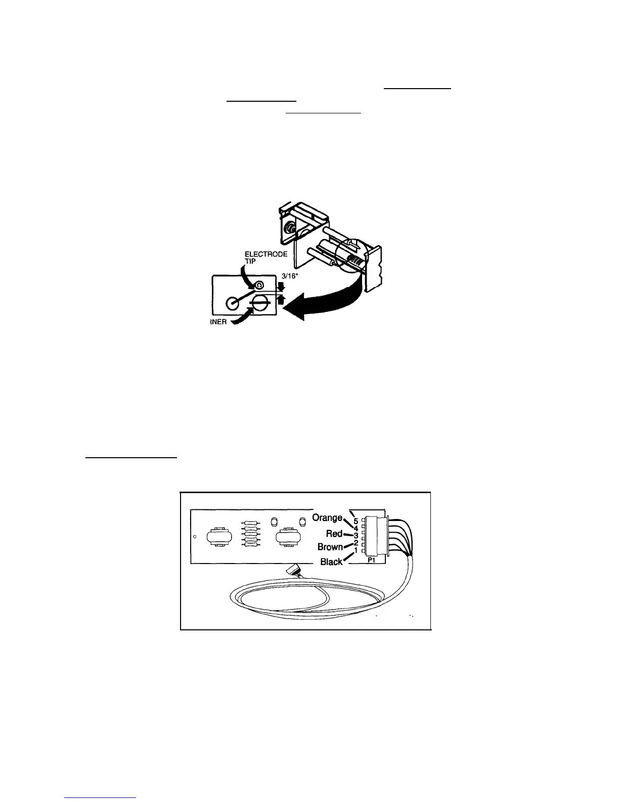
Do a visual check for cracks or breaks on the ceramic insulator. The spark gap must be set at three
sixteenths
(3/16”)
of an inch and tip of electrode above the slots in the burner.
BUR
. .
UPPER CIRCUIT BOARD
NOTE: The PAL tester will allow for proper testing of the integrity of the upper and lower circuit boards.
PAL is available from your
Dometic
parts distributor.
With
main
ON/OFF switch on display panel
in
OFF position:
Check for DC voltage at Plug
1,
Terminal 4 (orange wire) and terminal 5 (red wire) negative (-) DC on
the
lower circuit board.
If no voltage, then check fuse condition. Check for DC voltage between J4
and J10 terminals on the lower circuit board.
Green,
,
Next, check for DC voltage at the upper circuit board between terminal 4 (orange wire) and terminal 3
(red wire) which is negative (-) DC. If no voltage, and your previous check proved voltage at the lower
circuit board between these wires, replace the cable assembly.
With main ON/OFF switch on display panel in
ON
position:
Check for DC volts between terminal 3, red wire (-) negative and terminal 5 (green wire) and
terminal 1 (black wire). If there is no voltage, the ON/OFF switch on upper circuit board is defective.
 Loading...