A.
B.
r
DC VOLT:
ALL TESTS ARE TO BE DONE WITH THE REFRIGERATOR IN THE COOLING MODE.
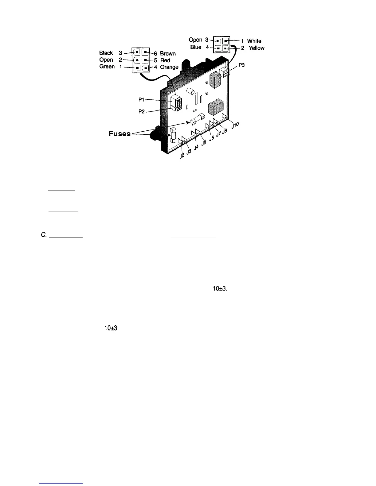
Measure volts between terminal J4 and the ground strip.
AC MODE:
Check that incoming AC voltage is present at terminals J5 and J6 on the circuit board.
Check for voltage at the heating element connection terminals J7 and J8 on the circuit board. If no
voltage is present, check the 5 amp AC and 3 amp DC fuses.
“. GAS MODE:
First, check for voltage during
trial-for-ignition
at Plug 3, Terminals 1 (white wire) and
2 (yellow wire) to the solenoid. If no voltage is present, change the circuit board. If voltage is present,
check for voltage at the solenoid.
Check for voltage to the igniter. If no voltage is present, check the wires. If good, then change the
circuit board.
If flame extinguishes during the cooling mode, the circuit board will not supply voltage to Plug 3,
Terminal 4 (blue wire) until the millivolts have decreased to
10*3.
To check the flame sense circuit of the lower circuit board, measure the millivolts between J3 termi-
nal and the other wire connection from the thermocouple. The millivolt meter should read between 25
to 35 millivolts with the gas flame burning. Turn the manual shutoff valve to OFF and watch the
millivolt reading as it drops. Note the millivolt reading when Plug 3, terminal 4 (blue wire) receives
power. It should be
lo*3
millivolts or 7 to 13.
DOOR SWITCH (Only on Models Equipped with Interior Lights)
When
the switch arm is depressed, there should not be continuity. When the switch arm is NOT de-
pressed, there should be continuity.
FUSES
The 3 amp DC fuse is designed to protect the circuit board from internal shorts. The 5 amp AC fuse
is designed to protect the integrity of the AC heater circuit from shorts.
11
 Loading...