66
Dometic
®
MANUAL
Refrigerators
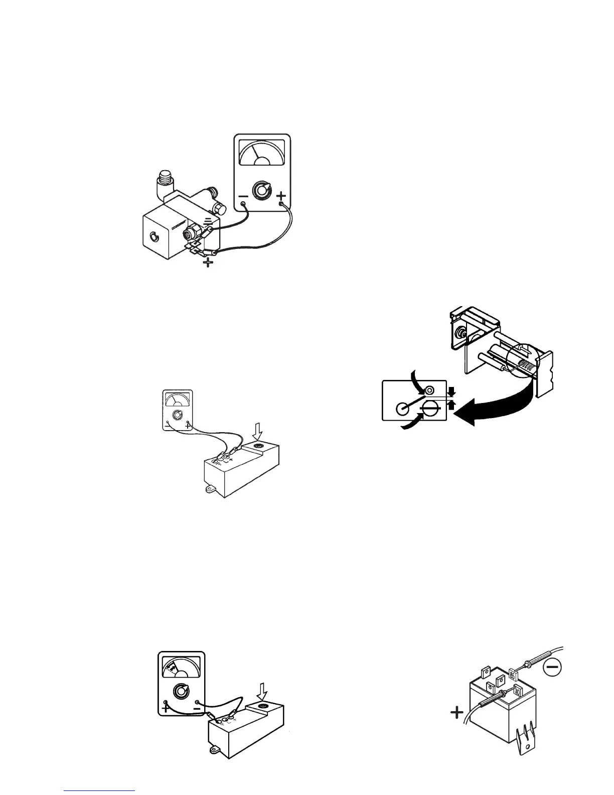
Check the solenoid coil with a properly calibrated ohm
meter. Remove the connector from the solenoid and
measure the resistance across the upper and lower
terminals. The proper reading would be 20 ohms
with tolerance range of ten percent.
Once flame is lit, the thermo-
couple produces the
voltage to keep the
valve open. If for any
reason the thermo-
couple does not
provide enough
current to the valve,
it will close, stopping
the flow of gas. To
check this portion of
the solenoid valve
assembly, verify the thermocouple is good,
the tip is clean and the receptacle in the
solenoid valve assembly is clean. If the thermocouple
checks good, then replace the solenoid valve assembly.
NOTE: If the solenoid ohms check shows an open coil,
the refrigerator will not operate on any mode.
IGNITERIGNITER
IGNITERIGNITER
IGNITER
The igniter is an elec-
tronic device that
produces high voltage
to create a spark at
the burner, only on
gas mode. It also
produces and in-
creased DC voltage
at the "L" terminal
which is a signal to
the circuit board that
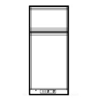
a spark has been produced. First, verify proper voltage
at the positive (+) and ground (–) terminals. The reading
should be within one volt of incoming voltage at the main
terminal block. A voltage drop of more than one volt
would indicate a loose connection or a circuit board
problem.
Next, disconnect DC power at refrigerator terminal block.
Remove high voltage cable from igniter. Reconnect DC
power — the igniter should produce a sparking sound. If
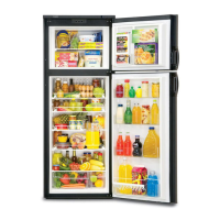
not, replace the igniter. With the igniter producing spark,
connect meter leads to "L" and ground (–) terminals on
the igniter, with the meter
set on 20 volts DC range
or lower. The meter
should read a pulsating
voltage. If not, replace the
igniter.
NOTE: If a spark is not
produced within 10
seconds, the gas flame
warning lamp will illumi-
nate. If spark is produced it will take three minutes for
lamp to illuminate.
If all of the previous checks are correct, the igniter is
good – do not replace.
HIGH VOLTAGE CABLEHIGH VOLTAGE CABLE
HIGH VOLTAGE CABLEHIGH VOLTAGE CABLE
HIGH VOLTAGE CABLE
Disconnect DC power at refrigerator terminal block.
Disconnect high voltage cable from electrode. Recon-
nect DC power. If sparking starts, cable is good.
If no sparking, disconnect DC power. If
sparking sound from igniter, then replace high voltage
cable.
ELECTRODEELECTRODE
ELECTRODEELECTRODE
ELECTRODE
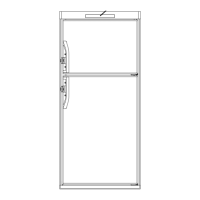
First, do a visual check for cracks or breaks on the
ceramic insulator. Verify the mounting bracket is at-
tached properly to the electrode. If either of above is
found, replace the electrode. The spark gap must be set
at three sixteenths (3/16") of
an inch and tip of electrode
above the slots in the
burner.
If igniter and high
voltage cable are
good and there
is no spark at
the tip of the
electrode,
replace the
electrode.
THERMOCOUPLE
The thermocouple is a component extending above the
burner assembly so the tip is in the path of the flame. In
normal operation, it will produce 14 to 30 millivolts DC.
The check thermocouple, use a known goo safety valve
and attach to the thermocouple. Next supply flame to tip
of thermocouple for 2 to 3 mimutes while depressing
safety valve. Remove flame and release safety valve.
The valve should hold for at least 30 seconds. If it does
not hold safety valve open for 30 seconds, replace
thermocouple. If it does hold for 30 or more seconds,
thermocouple is good - do not replace it. NOTE: Be sure
the tip on the thermocouple is clean.
RELAYRELAY
RELAYRELAY
RELAY
The relay controls the circuit to the DC heater. The
load (amps) of the DC heater goes through
the relay. Verify that DC volts to
the terminal block is 13.3 or
more.
HIGH VOLTAGE
ELECTRODE
TIP
3/16"
BURNER