Dometic
®
MANUAL
Refrigerators
69
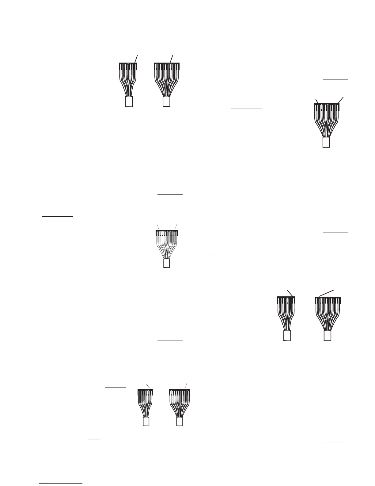
With the AC/gas function
switch manually depressed:
Continuity should be indicated
between the blue terminal on
the 7-pin connector to the blue
terminal on the 10-pin connec-
tor.
With the AC/gas function
switch NOT depressed:
A reading would NOT be
indicated.
NOTE: If the check on the AC/gas function switch is not
correct, verify the wire harness has continuity. If the wire
harness is good, replace the upper circuit board.
5. AC/GAS FUNCTION LAMP (Only on 3-Way Mod-
els):
NOTE: The following checks should be made on the
upper circuit board and harness assembly BEFORE
replacing the upper circuit board or wiring harness.
These checks are to be done with the wiring harness
REMOVED from the lower circuit
board and the ON–OFF switch
turned to "ON".
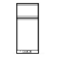
Measure resistance between the
brown terminal on the 10 pin connec-
tor (negative [–] lead from meter) to the
gray terminal on the 10-pin connector
(positive [+] lead from meter). The
proper resistance is approximately
26,000 ohms.
NOTE: If the check on AC/gas function lamp is not
correct, verify the wire harness has continuity. If wire
harness is good, replace the upper circuit board.
6. GAS FUNCTION SWITCH
NOTE: The following checks should be made on the
upper circuit board and harness assembly BEFORE
replacing the upper circuit board or wiring harness.
The checks are to be done with the wiring harness
REMOVED from the lower circuit board and the ON-
OFF switch turned to "ON".
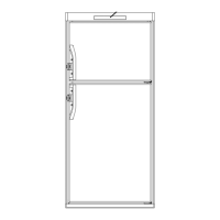
With the gas function switch
manually depressed: CONTI-
NUITY should be indicated
between the violet terminal on
the 10-pin connector to the blue
terminal on the 7-pin connector.
With the gas function switch
NOT depressed:
A reading would NOT be indi-
cated.
NOTE: If the check on gas function switch is not
GRAY
BROWN
correct, verify the wire harness has continuity. If wire
harness is good, replace the upper circuit board.
7. GAS FUNCTION LAMP
NOTE: The following checks should be made on the
upper circuit board and harness assembly BEFORE
replacing the upper circuit board
or wiring harness. These checks
are to be done with the wiring
harness REMOVED from the
lower circuit board, and the ON–
OFF switch turned to "ON".
Measure resistance between the
brown terminal on the 10-pin
connector (negative [–] lead
from meter) to the white terminal
on the 10-pin connector (positive
[+] lead from meter). The proper ohms resistance is
approximately 26,000 ohms.
NOTE: If the check on gas function lamp is not
correct, verify the wire harness has continuity. If wire
harness is good, replace the upper circuit board.
8. AC MODE LAMP AND SWITCH
NOTE: The following checks should be made on the
upper circuit board and harness assembly BEFORE
replacing the upper circuit board or wiring harness.
These checks are to be done with the wiring harness
REMOVED from the lower circuit board, and the ON-
OFF switch turned to "ON".
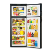
With the mode switch (?) manually depressed:
Resistance should be
indicated between the
brown terminal on the
10-pin connector
(negative [–] lead from
meter) to the red
terminal on the 7-pin
connector (positive [+]
lead from meter). The
proper resistance is
approximately 26,000
ohms.
With the mode switch (?) NOT depressed: A
reading would NOT be indicated.
NOTE: If the check on AC mode lamp and switch is
not correct, verify the wire harness has continuity. If
wire harness is good, replace the upper circuit board.
9. 12-VOLT MODE LAMP & SWITCH (Only on 3-Way
Models)
NOTE: The following checks should be made on the
upper circuit board and harness assembly BEFORE
replacing the upper circuit board or wiring harness.
These checks are to be done with the wiring harness
REMOVED from the lower circuit board, and the ON-
BROWN
BROWN