70
Dometic
®
MANUAL
Refrigerators
BROWN
ORANGE
YELLOW
GREEN
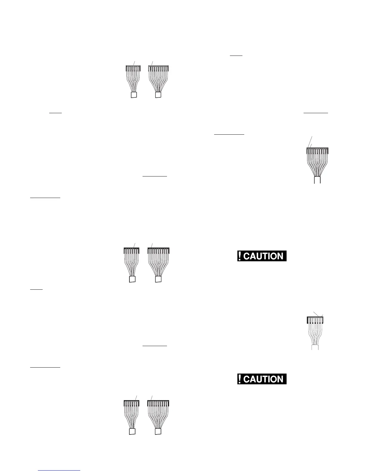
With the mode switch (?) manually depressed:
An ohms reading should be
indicated between the brown
terminal on the 10-pin connector
(negative[–] lead from meter) to
the orange terminal on the 7-pin
connector (positive [+] lead from
meter). The ohms reading should
be approximately 26,000. You
should NOT have a reading unless the mode switch
(?) is depressed.
NOTE: If the check on 12-volt mode lamp and switch
is not correct, verify the wire harness has continuity.
If wire harness is good, replace the upper circuit
board.
10. Delay Mode Lamp and Switch
NOTE: The following checks should be made on the
upper circuit board and harness assembly BEFORE
replacing the upper circuit board or wiring harness.
The checks are to be done with the wiring harness
REMOVED from the lower circuit board, and the
OFF-ON switch turned to "ON".
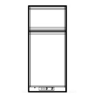
With the mode switch (?) manually depressed:
Resistance should be indicated between the brown
terminal on the 10-pin connector (negative [–] lead
from meter) to the yellow termi-
nal on the 7-pin connector
(positive [+] lead from meter).
The proper resistance is approxi-
mately 26,000 ohms.
With the mode switch (?) NOT
depressed: A reading would
NOT be indicated.
NOTE: If the check on the delay mode lamp and
switch is not correct, verify the wire harness has
continuity. If wire harness is good, replace the upper
circuit board.
11. Gas Mode Lamp and Switch:
NOTE: The following checks should be made on the
upper circuit board and harness assembly BEFORE
replacing the upper circuit board or wiring harness.
The checks are to be done with the wiring harness
REMOVED from the lower circuit board, and the ON-
OFF switch turned to "ON".
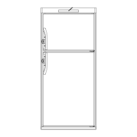
With the mode switch (?) manually depressed:
Resistance should be indicated
between the brown terminal on
the 10-pin connector (negative [–
] lead from meter) to the green
terminal on the 7-pin connector
(positive [+] lead from meter).
The proper resistance is approxi-
mately 26,000 ohms.
With the mode switch (?) NOT depressed: A
reading would NOT be indicated.
NOTE: If the check on gas mode lamp and switch is
not correct, verify the wire harness has continuity. If
wire harness is good, replace the upper circuit board.
12. Gas Flame Warning Lamp:
NOTE: The following checks should be made on the
upper circuit board and harness assembly BEFORE
replacing the upper circuit board or wiring harness.
The checks are to be done with the wiring
harness REMOVED from the lower circuit
board, and the OFF-ON switch turned to
"ON".
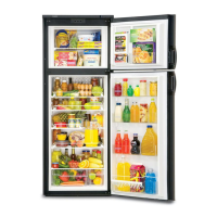
Measure resistance between the brown
terminal on the 10-pin connector (nega-
tive [–] lead from meter) to the black
terminal on the 10-pin connector (positive
[+] lead from meter). The proper resis-
tance is approximately 22,000 ohms.
NOTE: If the check on gas flame warning lamp is not
correct, verify the wire harness has continuity. If wire
harness is good, replace the upper circuit board.
CIRCUIT BOARD
The circuit board controls all modes of operation.
1.
THESE PROCEDURES MUST BE FOLLOWED
IN SEQUENCE AND AT THE PROPER TERMI-
NALS OR DAMAGE TO THE BOARD WILL
RESULT.
Before any checks are to be done, be sure proper
DC volts are to the board. Measure
volts between yellow terminal on the 6-
pin connector (positive [+] lead from
meter) to green terminal on 6-pin
connector (negative [–] lead from
meter). Voltage should be the same as
at the positive (+) and negative (–)
terminal block. If not, check the fuse
and wiring.
2.
THESE PROCEDURES MUST BE FOLLOWED
IN SEQUENCE AND AT THE PROPER TERMI-
NALS OR DAMAGE TO THE BOARD WILL
RESULT.
BLACK
BROWN
GREEN