Dometic
®
MANUAL
Refrigerators
71
For AC heating element operation, check that voltage
is present between the large black and large white
wire at the circuit board. If voltage is below 100 volts,
the circuit board will select another mode. If voltage
is above 100 volts, check that AC volts are present at
the heating element connection. If no voltage is
present, change the circuit board.
NOTE: Before installing a new circuit board, correct
the cause of the failure, most likely it is the heating
element or wiring.
If voltage is present, DO NOT CHANGE THE CIR-
CUIT BOARD. Check the following components:
heating element, upper circuit board, thermostat and
wiring.
3.
THESE PROCEDURES MUST BE FOLLOWED
IN SEQUENCE AND AT THE PROPER TERMI-
NALS OR DAMAGE TO THE BOARD WILL
RESULT.
For DC heating element operation, first check the
IGN lock terminal for a voltage reading of more than
4 volts. If voltage is below 4 volts, correct wiring
problem. If voltage is 4 or more, next check voltage
between the positive (+) and negative (–) terminals
on the main terminal block. If voltage is below 13.3
(plus or minus [±] .3 volts), the DC heating element
will not be energized, the circuit board will select gas
mode; correct the power source problem. If voltage is
above 13.6 and IGN lock terminal is receiving more
than 4 volts, verify the IGN lock voltage is reaching
the circuit board by checking the black
terminal on the 6-pin connector. If no
voltage is present, correct wire and or
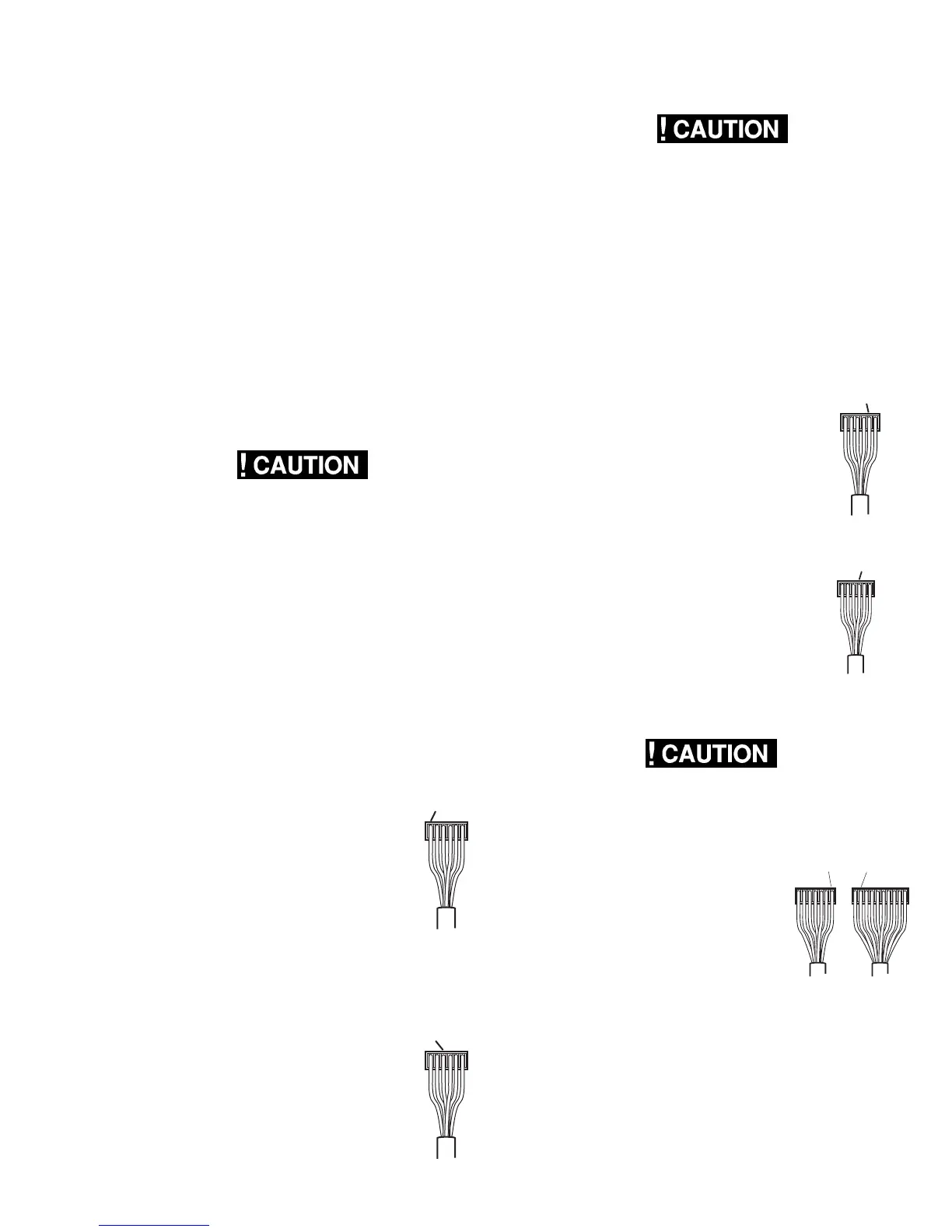
connection. If voltage is present, next verify
the voltage is reaching the circuit board by
checking between the yellow terminal on the
6-pin connector (positive [+] lead from
meter) to the grounding strip (negative [–]
lead from the meter). If no voltage is
present, check the fuse (see Section 4.11).
If voltage is present but BELOW 13.6,
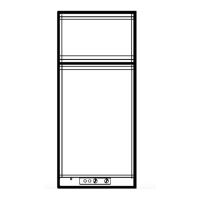
correct the wire and/or connection problem. If voltage
is ABOVE 13.6, check for voltage between the red
terminal on the 6-pin connector (positive
[+] lead from meter) and the grounding
strip (negative [–] lead from meter). If no
voltage is present, replace the circuit
board. If voltage is present, the circuit
board is NOT defective, do not replace.
4.
THESE PROCEDURES MUST BE FOLLOWED IN
SEQUENCE AND AT THE PROPER TERMINALS OR
DAMAGE TO THE BOARD WILL RESULT.
Before you check the circuit board for gas operation,
verify these components are good:
Igniter High Voltage Cable
Electrode Solenoid
Upper Circuit Board
Thermostat (
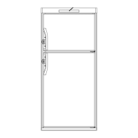
Also be sure NO voltage is present at the IGN lock
terminal, and delay mode is not activated. First,
check that voltage in excess of 10.5 volts is between
the yellow terminal on the 6-pin connector
(positive [+] lead from meter) to the ground
strip (negative [–] lead from meter). If less
than 10.5 volts, correct wiring and/or power
source problem.
Next, check for the pulse voltage from the
igniter at the orange terminal on the 6-pin
connector (negative [–] lead from meter)
and the ground strip (positive [+] lead from
meter). If there is no signal voltage, check
the igniter and the orange wire and
connections. If signal voltage is present,
next check for voltage on the solenoid
wires at the circuit board. Positive lead
from meter to the gray wire and negative
lead from the meter to the black wire. If
voltage is 9.5 volts or more, the circuit
board is good. Do not replace. If no voltage
is present, replace the circuit board.
5.
THESE PROCEDURES MUST BE FOLLOWED IN
SEQUENCE AND AT THE PROPER TERMINALS OR
DAMAGE TO THE BOARD WILL RESULT.
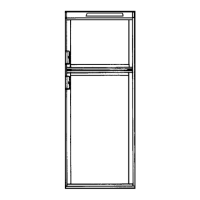
This check is to determine if the
circuit board is providing voltage to
the upper circuit board. Measure
between the brown terminal on the
10-pin connector (positive [+] lead
from meter) to the blue terminal on
the 7-pin connector (negative [–]
lead from meter). A voltage reading
indicates the circuit board is good. If
no voltage is present, replace the
circuit board. NOTE: Before changing the circuit
board, be sure all troubleshooting steps have been
followed.
FUSE
The fuse is to protect the circuit board. To check the
fuse, remove it from the holder and do a continuity
check. If no continuity, replace it with a proper 3 amp
time delay fuse.
BLACK
6 Pin
RED
6 Pin
YELLOW
6 Pin
ORANGE
6 Pin
BROWNBLUE
10 Pin7 Pin