9
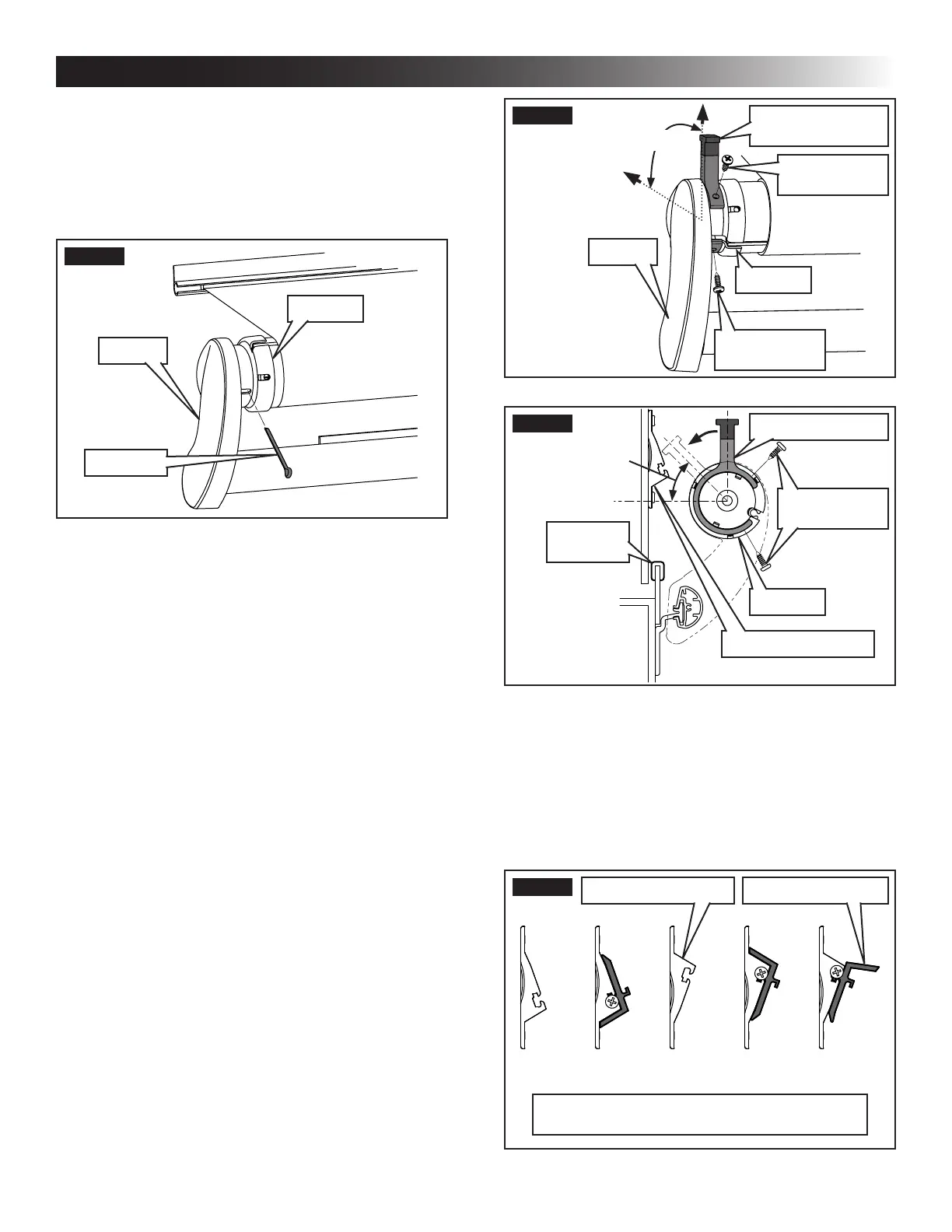
FIG. 16
Wall
Up
90°
Bumper
(Anti-Billow Stop)
#10 Screw
(Self Drilling)
#10 Screw
(Self Drilling)
End Cap
LH Arm
FIG. 17
Anti-Billow Stop
#10 Screw
(Self Drilling)
Anti-Billow Bracket
End Cap
Edge
Protector
45°
2. Determine required conguration of anti-billow
bracket and spacer (spacing from RV wall) to
ensure anti-billow stop will NOT rotate past a
45° angle (toward RV wall). See (FIG. 17) &
(FIG. 18).
The anti-billow bracket and anti-billow
spacer can be congured for a spacing
range of 5/16″ to 1 1/2″.
FIG. 18
3/4″ 1″ 1 1/2″1/2″5/16″
Anti-Billow Bracket / Spacer Conguration
(Spacing From RV Wall)
Anti-Billow SpacerAnti-Billow Bracket
plicable) from LH torsion rod (at LH end cap).
See (FIG. 15).
Removing cotter pin will release factory
preset tension. To facilitate removal, ro-
tate the fabric roller tube (as if unrolling
awning) by pulling bottom of tube toward
you while pulling on cotter pin.
FIG. 15
End Cap
LH Arm
Cotter Pin
10. Repeat step (9) for RH end.
D. Install Anti-Billow Stop
1. Cotter pins MUST be removed
from Slide Topper end caps BEFORE operating
slide out room. Otherwise, damage to the Slide
Topper and/or slide out room will occur.
With slide out room (and awning) still closed,
place anti-billow stop on end cap. See (FIG. 16)
& (FIG. 17).
a. Determine onto which end cap anti-billow
stop will be installed.
Slide Toppers 198″ or wider REQUIRE
an anti-billow stop (and bracket) at
BOTH end caps, and a cradle kit for
center support. See “B. Optional Com-
ponents & Kits” on page (4) to or-
der.
b. Place anti-billow stop on desired end cap
with opening facing AWAY from awning rail
(when bumper is pointed straight up).
c. Position anti-billow stop with bumper pointed
straight up (vertical). Then tape in place.
If either screw hole (in anti-billow stop)
interferes with existing holes or open-
ings in end cap, rotate anti-billow stop
away from RV wall (no more than 30°
from vertical position) before taping.
INSTALLATION
 Loading...