Technical description SMP439, 439-08
12
• Alterations to the product without express permission from the manufacturer
• Use for purposes other than those described in this manual
Dometic reserves the right to change product appearance and product
specifications.
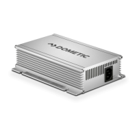
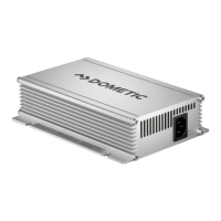
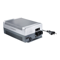
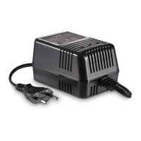
5 Technical description
The battery charger charges batteries that are used on board vehicles to generate
power or supplies them with a retention voltage so that they do not discharge. It is
automatically charging the batteries and maintaining them with float voltage after
charging has finished. Therefore the battery charger can be plugged in during lon-
ger periods of time without damaging the batteries.
A control lamp on the device enables constant monitoring in the battery charger.
The device has the following protective systems:
• Overvoltage protection
• Overheating protection
• Overload protection
The SMP439 device can also be connected to a LIN/CI bus master using two con-
nections through which a battery sensor (IBS) can be queried. The device can also be
used without a battery sensor.
The SMP439-08 device can also be connected to a LIN/CI bus master. Only output
A1 can be controlled via LIN/CI bus, A2 works in master mode.
The cooling system uses convection cooling to surrounding air.
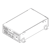
5.1 Connections and controls
No. in
fig. 1, page 3
Explanation/function: SMP439
1 Input for AC power supply
2 LIN2 connection socket
3 LIN1 connection socket
4 Start relay socket
5 Status LED
6 LIN bus connection socket / Temperature Sensor
 Loading...