2
CONTENTS
1. GENERAL INFORMATION
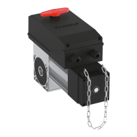
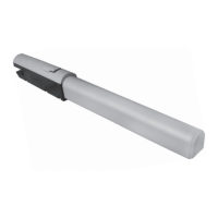
The electromechanical linear operator Swing-3000/5000 is intended for automation of a street double-leaf swinging gate with
a load-bearing structure. The body of the operator, which consists of two silumin parts, houses a motor, a reducer and a lead
screw.
The operator is equipped with built-in electrical limit switches for opening and closing.
A self-blocking system, consisting of a worm gear and a planetary gearbox blocks the gate leaves, if the motor is off. The easy-
to-use and safe release system allows the gate leaves to be opened/closed manually, in case of a power cut or control unit failure.
Operation of the automatic system is controlled from a remote control unit in a shockproof hermetic case.
1.1. RANGE OF USE
Leaf width, m Leaf weight, kg
2.00 1 000
2.50 800
3.00 600
4.00 500
5.00 400
Leaf width, m Leaf weight, kg
2.00 800
2.50 600
3.00 400
Swing-3000 Swing-5000
CONTENTS
1. GENERAL INFORMATION ............................................................................2
1.1. Range of use .................................................................................2
1.2. Technical specifications .........................................................................3
1.3. Operator package ..............................................................................3
2. SAFETY INSTRUCTIONS ............................................................................3
3. OPERATOR UNIT ..................................................................................5
4. OPERATOR INSTALLATION ..........................................................................5
4.1. Tools ........................................................................................5
4.2. Installation layout ..............................................................................6
4.3. Inward gate opening ............................................................................7
4.4. Outward gate opening ...........................................................................8
5. ELECTRICAL CONNECTIONS .........................................................................8
5.1. Control block wiring diagram .....................................................................8
5.2. Control block terminals .........................................................................8
6. EXTREME POSITIONS ADJUSTMENT ..................................................................10
6.1. Preparation ..................................................................................10
6.2. Open position ................................................................................10
6.3. Closed position ...............................................................................10
7. OPERATOR PROGRAMMING ........................................................................11
7.1. Basic programming ...........................................................................11
7.2. Advanced programming ........................................................................11
7.3. Operation time programming ....................................................................11
8. PROGRAMMING OF REMOTE CONTROLS ..............................................................12
9. RELEASE OPERATION .............................................................................12
10. MAINTENANCE ..................................................................................12
11. TROUBLESHOOTING ..............................................................................13
 Loading...