8
ELECTRICAL CONNECTIONS
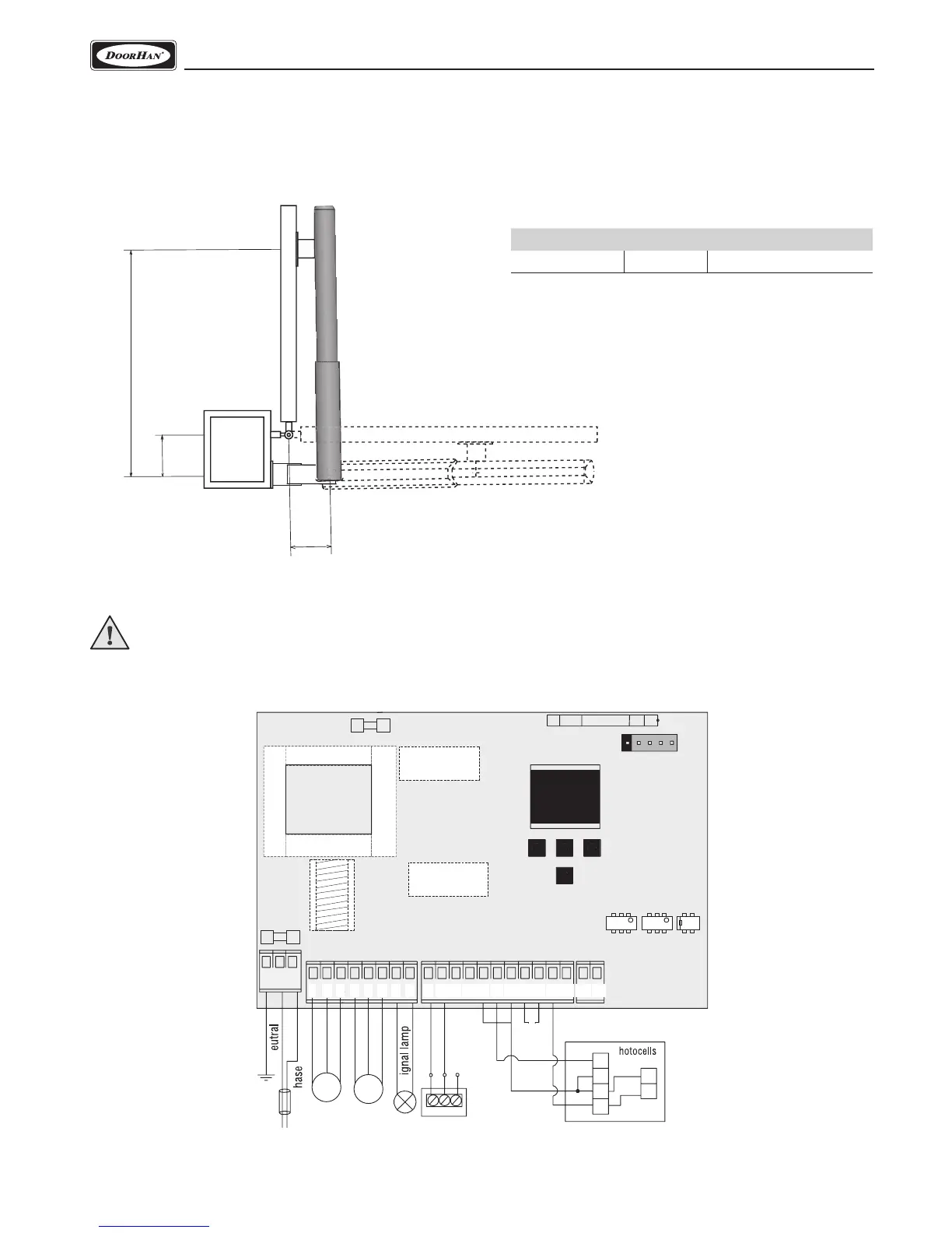
5. ELECTRICAL CONNECTIONS
WARNING! The cable wires must be protected from contact with any rough or sharp parts. All connections shall be made
only when power is off.
5.1. CONTROL BLOCK WIRING DIAGRAM
4.4. OUTWARD GATE OPENING (SWING-5000)
1) Position the rear bracket in accordance with the dimensions A and B, listed in the table.
2) Install and fasten the rear bracket to the pole using an additional bracket.
3) Open the gate, measure distance D and fasten the front bracket to the gate leaf.
Наружняя сторона объекта
Внутренняя сторона объекта
Дополнительный
кронштейн
D
B
A
External side of the object
Internal side of the object
Additional
bracket
1 2 345 678 9 10 11 13 14 15 16 17 18 19 20 2112
P
ENL
COM
OP CLLAMP
S-B-S
PED
OP CL
COM STOP +24V
S.Lock
COM OP CL
FOTO
2
3
4
5
2
2
I
COM
+
+
-
F
Tr
COMNO
NC
1
2
3
4
5
6 7 8
9
10 11 13 14 15 16 17 18 19 20 2112
ENL
COM
OP CLLAMP
S-B-S
PED
OP CL
COM STOP +24V
S.Lock
COM OP CL
FOTO
3
1
R
COM
COM NO
NC
М1 М2
Key-button
Transformer
M1 M2
220–240 V
50 Hz
GND
+24
VCC
+24
GND
VCC
J1
J7
J4
J3
N
P
S
P
NC
(Normally
closed)
Opening angle A, mm B, mm D, mm
90 130 130 720
 Loading...