1506-065-K-6-17
6
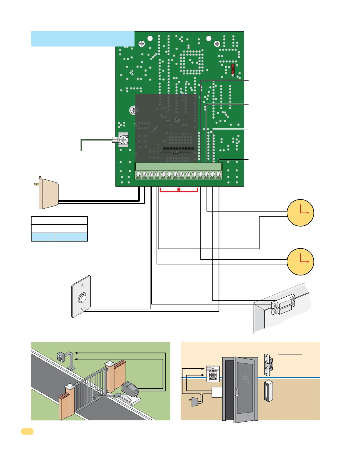
Basic Door Control ComponentsBasic Gate Control Components
Door Locks
Gate Operator
Magnetic lock is wired to
the Normally Closed (NC)
relay input.
Electric strike is wired
to Normally Open (NO)
relay input.
Gate Operator
is wired to
Normally Open
(NO) relay
input.
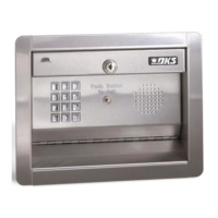
1504/1506
Keypad
1504/1506
Keypad
0
4 5 6
7 8 9
Power Input
Supplied Power
Transformer
16.5 VAC
20 VA
18 AWG
16 AWG
100 Ft.
200 Ft.
Wire Size MAX Distance
Keep power wiring as
short as possible.
Relay 1 and Relay 2 Input Options
Relay contacts are rated for 30 Volt, 1 amp maximum power.
Earth
Ground
Attach a separate 12 AWG wire to GND
(earth ground). Attach the other end of this
wire to a good earth ground.
This can be a properly grounded metal
conduit, a cold water pipe, or a grounding
rod driven at least 10 feet into the soil.
A gooseneck post anchored or mounted on
concrete does not make a good ground.
Avoid any splices in wiring. If a splice is
made, it must be soldered and sealed in a
watertight junction box.
• Current Draw with 16 Volt AC
Input: 100mA at rest; 275mA
with relay activated.
• Current Draw with 12 Volt DC
Input: 30mA at rest; 145mA
with relay activated.
• Current Draw with 24 Volt DC
Input: 50mA at rest; 165mA
with relay activated.
Note: 12-24 VDC may also be used
to power the 1504/1506.
Note: A low voltage power surge suppressor
(P/N 1878-010) is recommended.
Power for electric strike or maglock
is NOT provided by the 1504/1506.
Use separate UL listed power supply.
Separate Lock Power
UL listed
Door
Lock
Relay 1 Input
for Door or Gate
Relay 2 Input
for Door or Gate
MASTER
CODE
ON
GND
1506-010
12345
6789
101112
13
14
123456789
10 11 12 13
14
14 - 10 - 16.5 VAC OR 12 - 24 VDC
13 - 10 - 16.5 VAC OR 12 - 24 VDC
12 - Low Voltage Common
11 - Low Voltage Common
10 - Relay 2 Normally Open (N.O)
9 - Relay 2 Normally Closed (N.C.)
8 - Relay 2 Common
7 - Relay 1 Normally Open (N.O)
6 - Relay 1 Normally Closed (N.C.)
5 - Relay 1 Common
4 - A switch closure to TERMINAL 11
will lock out all entry codes within the
TIME ZONE 1 lower and upper
boundary.
3 - A switch closure to TERMINAL 11
will lock out all entry codes within the
TIME ZONE 2 lower and upper
boundary.
2 - DOOR OPEN – A switch closure to
TERMINAL 12 will cause the relay
that is activated to deactivate
1 second after this input is activated.
Can also be used for alarm bypass.
1 - REQUEST TO EXIT – A switch
closure to TERMINAL 12 will activate
RELAY 1 for its programmed strike
time.
(NO)
Com
#12
#12
#2
#3
#4
#11
#11
#1
(NO) or (NC)
Com
0
4
56
1
23
7
89
6
9
12
External Time Clock
Time ZONE 1
6
9
12
External Time Clock
Time ZONE 2
Request to Exit
EXI
T
PUSH TO
Door Contact Switch
1.4 Terminal Wiring
Keypad MUST be
Properly Grounded!
 Loading...