31
MicroController Control System Systems Operation
NOTE:
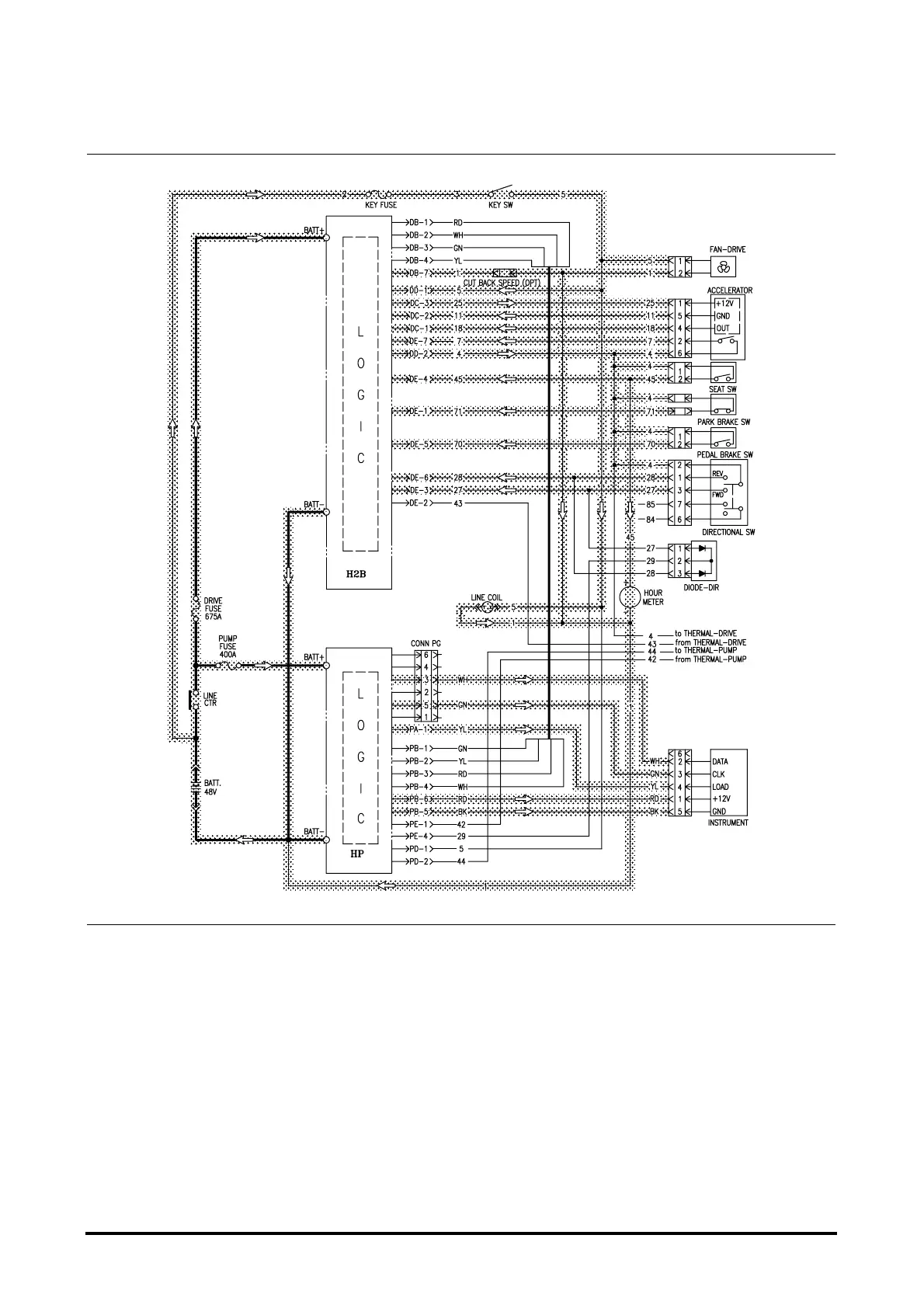
The circuit diagrams have shaded lines for
illustration of current flow in each circuit.
With the actuation circuit complete the logics
supplies a HIGH voltage (48 volts) to the direction
(F/R) switch at DD-2(wire #4). 12V is also
supplied to the power of accelerator at DC-3.
Releasing the park brake closes the park brake
switch and provides voltage to DE-1.
Selecting a direction will change the voltage from
0V to 48V on DE-3 for forward or DE-6 for reverse.
Depressing the accelerator pedal will cause the
accelerator analog voltage on DC-1.
With the forward direction seleted, current flows from
the logics DG-1 through forward direction contactor coil
to logic DG-5 back to battery negative. The forward
contactor tip closes.
Drive Control Circuit
Drive Circuit
Control Circuit



 To Next Page