32
MicroController Control System Systems Operation
NOTE:
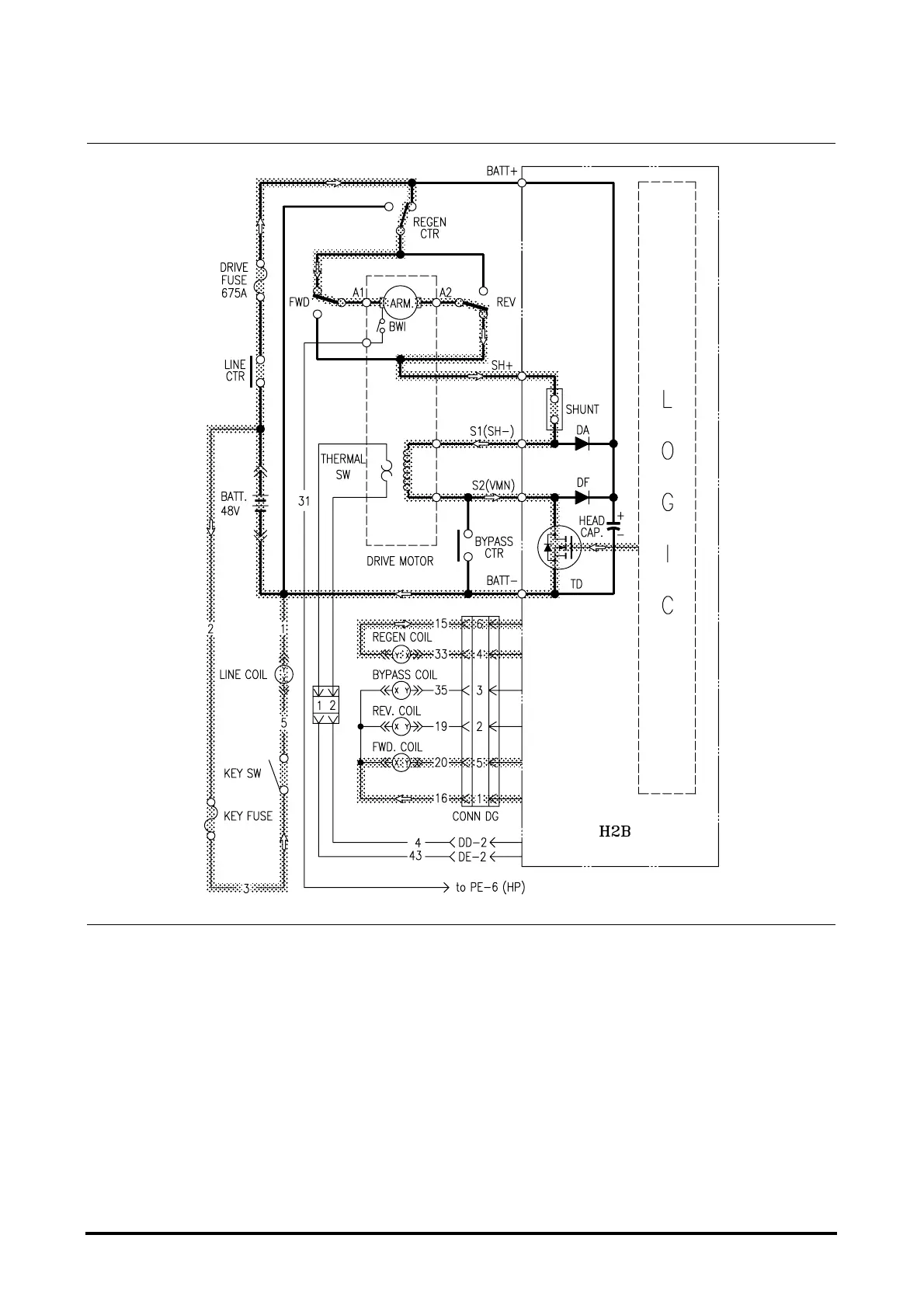
The circuit diagrams have shaded lines for
illustration of current flow in each circuit.
Other circuits can be activated at the same
time, but each one is shown separately to
illustrate current flow in each individual circuit.
The high amperage current, which provides the power
and torque necessary to drive the lift truck, flows in
this circuit. The speed of the drive motor is
controlled separately from the pump motor circuit by
the MicroController Control System.
To activate the drive circuit, the seat switch, key
switch and line contactor must be closed first.
The logic generates a positive pulsing voltage to the
gates of TD MOSFET.
If you select the direction switch to forward and push
down the accelerator pedal, regen contactor and for-
ward contactor will be activated. And logic will start to
generate a positive plusing voltage to the gate of TD.
With the MOSFET ON, high amperage motor current
can flow through regen contactor, forward contactor,
armature, reverse contactor, SHUNT, field and TD
back to battery negative.
Power Circuit
Drive MOSFET Gate Input Signals


 To Next Page