5. About the engine
93
4) Attach 12 connecting rod and piston assembly as the
same procedure.
14. Attach the oil suction pipe and the oil pump.
DV2213087A
1) Attach the oil suction pipe and the oil pump(D).
2) Tighten M8 fixing bolt(C) at a tightening torque 2.2 kgf·m.
3) Tighten 2 M8 fixing bolts(B) at a tightening torque
2.2 kgf·m.
4) Tighten 2 M8 fixing bolt(A) at a tightening torque
2.2 kgf·m.
15. Attach the oil pan.
DV2213086A
1) Attach the oil pan(B).
2) Tighten 20 M8 fixing bolts(A) at a tightening torque 2.2 ±
0.33kgf·m.
16. Change the engine position.
DV2213185A
1) Change the engine positon. The piston direction is
upward.
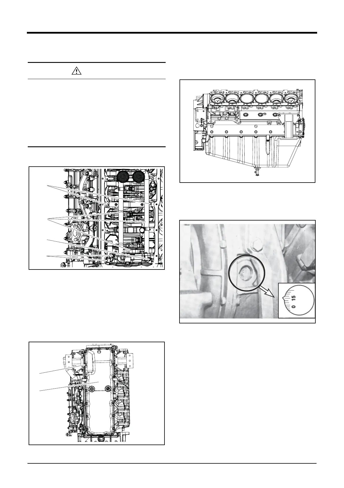
17. Adjust the fuel injection timing.
DV2213027A
1) Rotate the crankshaft so that the #1 cylinder piston may
be positioned at the top dead center(OT) and the #6
cylinder piston may be posiitioned at the valve overlap.
Note) In case of 8/12 cylinder engine, #6. cylinder is posi-
tioned at the valve overlap when #1. cylinder is posi-
tioned at the compression TDC(Top Dead Center).
Note) In case of 10 cylinder engine, #7. cylinder is positioned
at the valve overlap when #1. cylinder is positoned at
the compression TDC(Top Dead center).
2) Rotate the crankshaft until the yellow mark of the
camshaft gear is not shown.
3) Adjust the fuel injection timing with rotating the flywheel
to the engine rotating direction.
• Be careful to note the direction when attaching the
connecting rods and the connecting rod caps.
Ensure that the number engraved on the connecting
rods is same with that engraved on the connecting
rod caps and the assembly direction is same.
• Attacht the connecting rod and piston assembly
without contacting the crankshaft weight. Rotate
the crankshaft.