EasyManuals Logo

Doosan Vision DVSD-TT Series User Manual

Doosan Vision DVSD-TT Series
93 pages
To Next Page IconTo Next Page
To Previous Page IconTo Previous Page
Page #25 background imageLoading...
Page #25 background image
DOOSAN SERVO
20
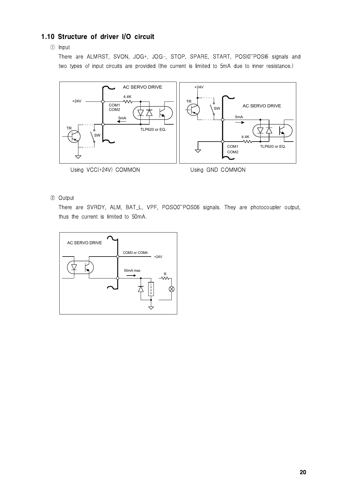
1.10 Structure of driver I/O circuit
Input
There are ALMRST, SVON, JOG+, JOG-, STOP, SPARE, START, POSI0~POSI6 signals and
two types of input circuits are provided (the current is limited to 5mA due to inner resistance.)
4.4K
TLP620 or EQ.
SW
TR
5mA
AC SERVO DRIVE
+24V
COM1
COM2
4.4K
TLP620 or EQ.
SW
TR
5mA
AC SERVO DRIVE
+24V
COM1
COM2
Using VCC(+24V) COMMON Using GND COMMON
Output
There are SVRDY, ALM, BAT_L, VPF, POSO0~POS06 signals. They are photocoupler output,
thus the current is limited to 50mA.
R
COM3 or COM4
L
O
A
D
+24V
50mA max
AC SERVO DRIVE

Table of Contents

Questions and Answers:

Question and Answer IconNeed help?

Do you have a question about the Doosan Vision DVSD-TT Series and is the answer not in the manual?

Doosan Vision DVSD-TT Series Specifications

General IconGeneral
BrandDoosan
ModelVision DVSD-TT Series
CategoryController
LanguageEnglish

Related product manuals