14
ED50/ED100/ED250 09-2021DL4617-003
dormakaba ED50/ED100/ED250 OHC Header
Setup and Troubleshooting Instructions
Chapter 7
System accessories
. System accessory electrical connections
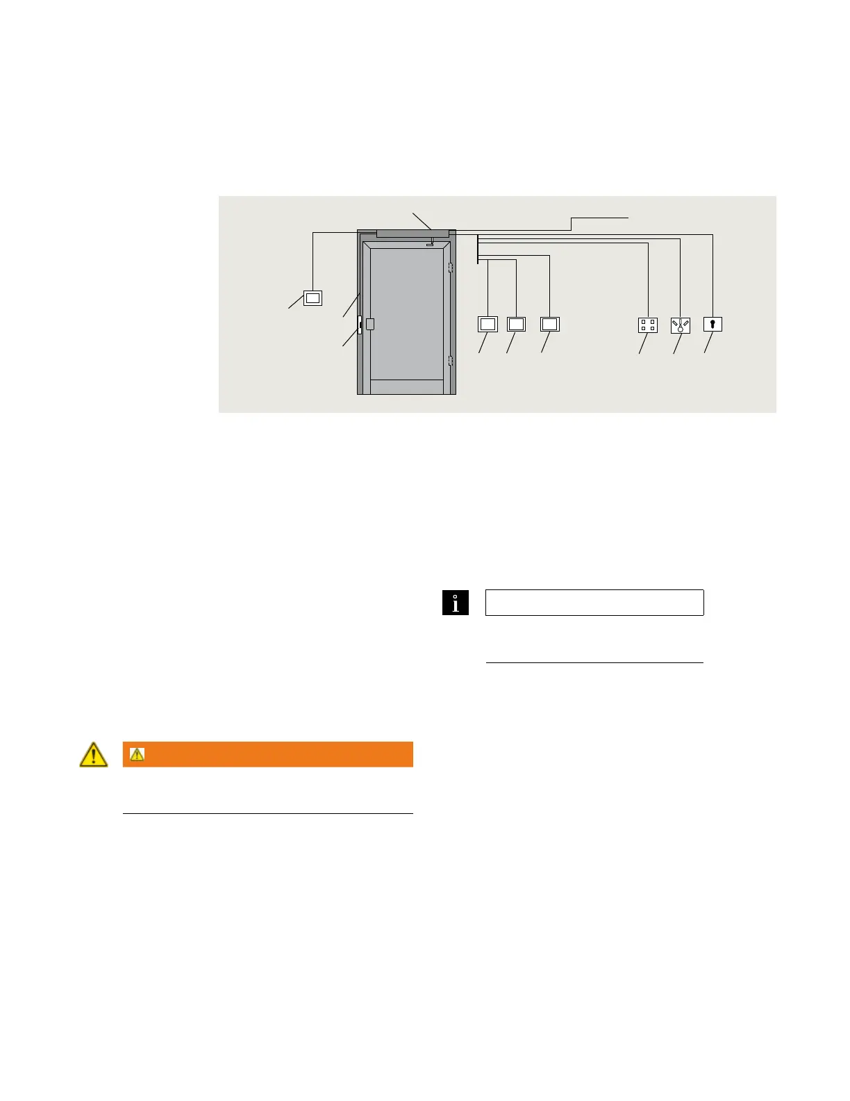
Fig. 5.1.1 Electrical connections, single door
.. Overview
ED/ED/ED operators are normally used with
system accessories available from dormakaba USA, Inc.
or other manufacturers.
.. Accessory electrical installation.
Electrical interfaces from system accessories used with
operator must be planned for. This includes routing of
wiring from accessories to operator.
.. System accessories, other
manufacturers.
dormakaba USA cannot guarantee compatibility for
other manufacturer's accessories. If any of these
accessories are used despite this caution, the operator's
full range of functions may be unavailable, or the
accessories may not function properly.
WARNING
Damage to operator or to connected device is
also possible!
.. ED power for accessories.
. Separate power supply required for accessories.
.. ED/ED power for accessories.
. Vdc, . A ( watts) is available from the
operator for external consumers (Fig. ..). This
supply has overcurrent protection. If additional
power is required, an external power supply must be
used.
. System accessories
1 External mode
switch, mechanical
2 External mode
switch, electronic
3 Key switch
4 Pushbutton, night /
bank
5 Pushbutton, interior
6 Pushbutton, exterior
7 Door locking device
8 Manual release
switch
9 ED50/ED100/
ED250
.. Activators
Typical activators:
. Pushbuttons, key switches
. Access control systems
. Telephone systems
. Intercoms
. Sensor automatic activators (ANSI/BHMA A.).
TIPS AND RECOMMENDATIONS
Refer to Chapter 4, Technical data
for electrical interface requirements.
.. Locking devices.
Typical locking devices:
. Electric strike plates
. Electromagnetic locks
. Electric locks
To insure that operator and locking device work safely
when connected together, locking device mus comply
with following:
. Operating voltage, power supply from operator,
Vdc, ± %.
. Operating voltage, external power supply,
Vdc/Vac maximum.
. Locking device relay contact, maximum load, A.
. Electric strike plate duty factor, % minimum.
. Motor lock duty factor, %.
1
8 x 18 AWG
8 x 0.8 mm
2
2 x 18 AWG
2 x 0.8 mm
2
2 x 18 AWG
2 x 0.8 mm
2
2 x 18 AWG
2 x 0.8 mm
2
4 x 18 AWG
4 x 0.8 mm
2
2 x 18 AWG
2 x 0.8 mm
2
2 x 18 AWG
2 x 0.8 mm
2
2 x 18 AWG
2 x 0.8 mm
2
3 x 12 AWG
3 x 4.0 mm
2
115 VAC power
2
4
5
6
3
7
8
9