EasyManuals Logo

Dorna EPS-EB Series User Manual

Dorna EPS-EB Series
34 pages
To Next Page IconTo Next Page
To Previous Page IconTo Previous Page
Page #10 background imageLoading...
Page #10 background image
10
9
1 8
15
Chapter II Wiring
2.1 Connector and terminal of servo driver
EPS-EB series servo driver connectors and terminals
Terminal mark
Name
Description
R, S, T
Main loop power input
terminal
Connect with three-phase AC supply.
L1, L2
Control loop power input
terminal
Connect with single-phase AC supply.
U, V, W
Servo motor connecting
terminal
Connected with the servo motor
Earth terminal
It is connected with power earth terminal and motor
earth terminal for grounding.
CN2
I/O connector
Connected with upper controller or RS485
CN3
Encoder connector
Connected with the motor encoder
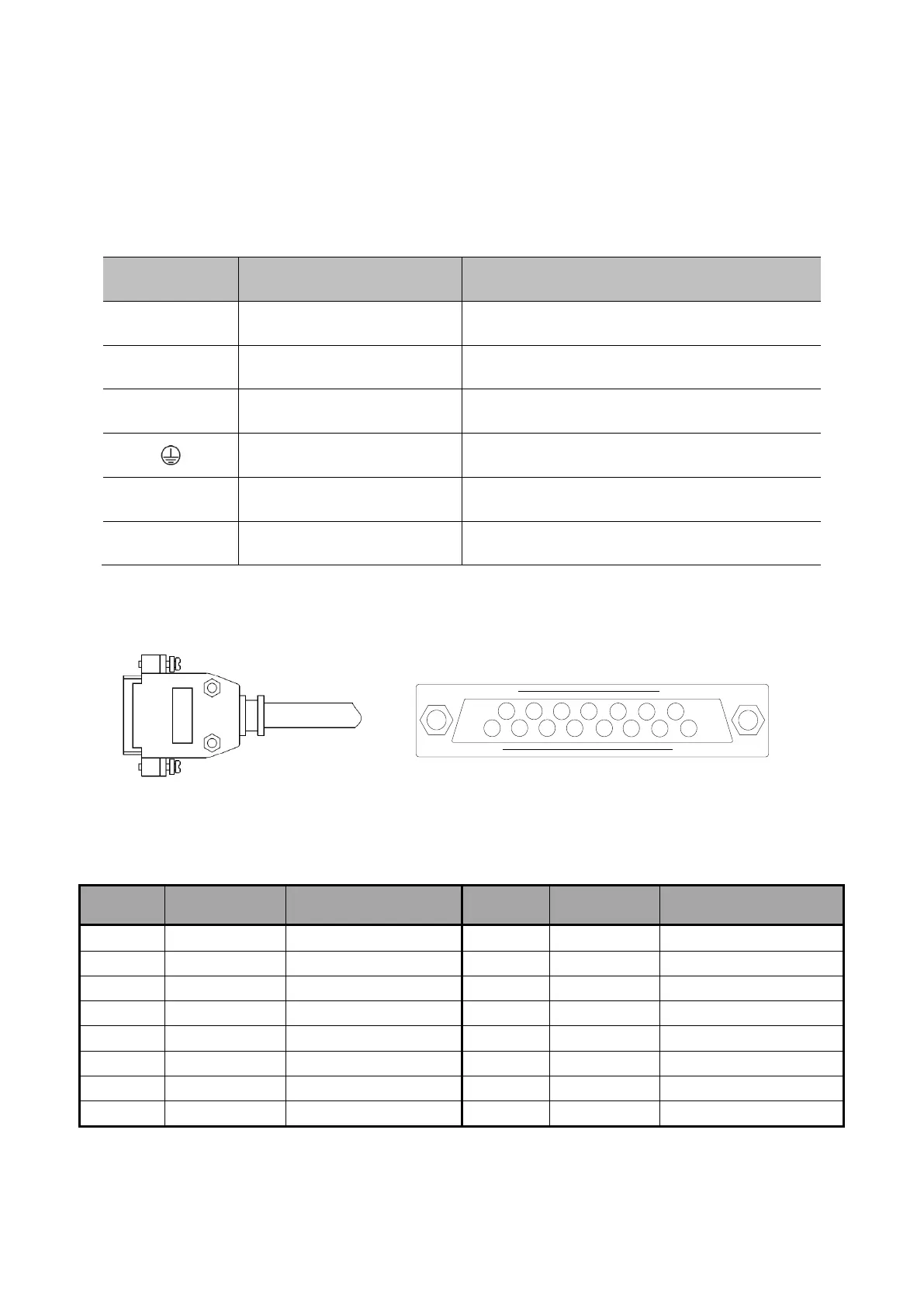
2.1.1 Appearance and signal of CN3 terminal
Appearance of CN3 terminal
Signal of CN3 terminal
Terminal
mark
Name
Function
Terminal
mark
Name
Function
9
A+
PG input A+ phase
6
U+
PG input U+ phase
1
A-
PG input A- phase
14
U-
PG input U- phase
2
B+
PG input B+ phase
5
V+
PG input V+ phase
10
B-
PG input B- phase
13
V-
PG input V- phase
3
Z+
PG input Z+ phase
12
W+
PG input W+ phase
11
Z-
PG input Z- phase
4
W-
PG input W- phase
7
+5V
PG supply +5V
8
GND
PG supply 0V
15
PE
Shielding

Questions and Answers:

Question and Answer IconNeed help?

Do you have a question about the Dorna EPS-EB Series and is the answer not in the manual?

Dorna EPS-EB Series Specifications

General IconGeneral
BrandDorna
ModelEPS-EB Series
CategoryController
LanguageEnglish

Related product manuals