EasyManuals Logo

Dorna EPS-EB Series User Manual

Dorna EPS-EB Series
34 pages
To Next Page IconTo Next Page
To Previous Page IconTo Previous Page
Page #11 background imageLoading...
Page #11 background image
11
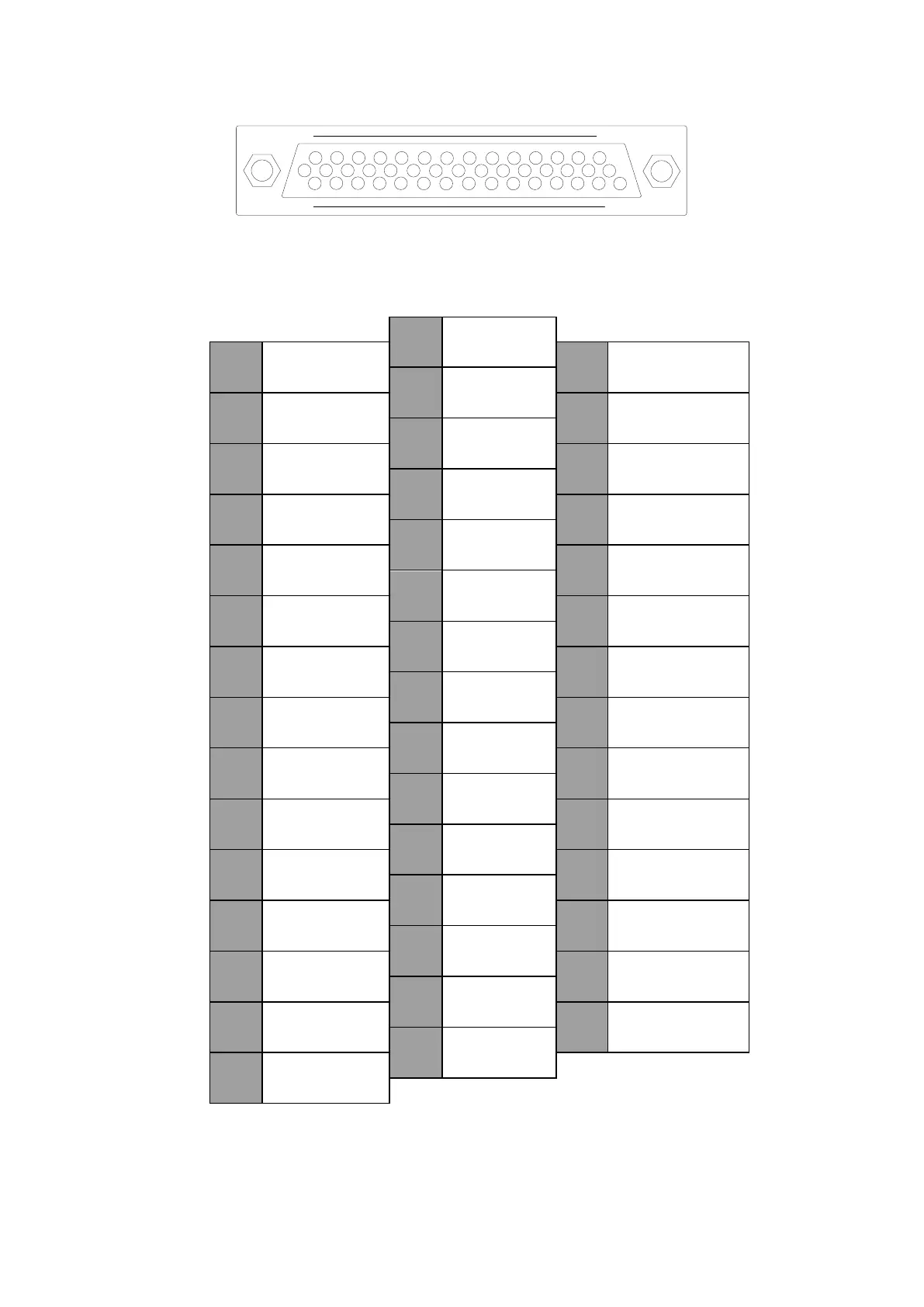
2.1.2 Appearance and signal of CN2 terminal
31
1
15
44
16
30
Appearance of CN2 terminal
Arrangement of CN2 terminal
16
RS+
1
CLE
31
17
RS-
2
INH
32
AGND
18
3
COIN
33
S_REF
19
CCWL
4
S_RDY
34
T_REF
20
CWL
5
ALM
35
DAOUT
21
A_CLR
6
36
AGND
22
COM+
7
BRK_OFF
37
23
ZEROSPD
8
ZO
38
PULS24+
24
S_ON
9
PULS+
39
SIGN24+
25
COM-
10
PULS-
40
COM-
26
C_MODE
11
SIGN+
41
27
TLC
12
SIGN-
42
28
ZSP
13
OZ+
43
29
OZ-
14
OB-
44
OA+
30
OA-
15
OB+
Notes:
1 Please do not use unoccupied terminal.
2 Please connect the shielding layer of input-output signal cable to the enclosure of connector. Conduct frame grounding
(FG) through the connector at servo driver side.
3 Above are default signal arrangements. Except ZO signal, all I/O signals can alter distributions through parameter
settings.

Questions and Answers:

Question and Answer IconNeed help?

Do you have a question about the Dorna EPS-EB Series and is the answer not in the manual?

Dorna EPS-EB Series Specifications

General IconGeneral
BrandDorna
ModelEPS-EB Series
CategoryController
LanguageEnglish

Related product manuals