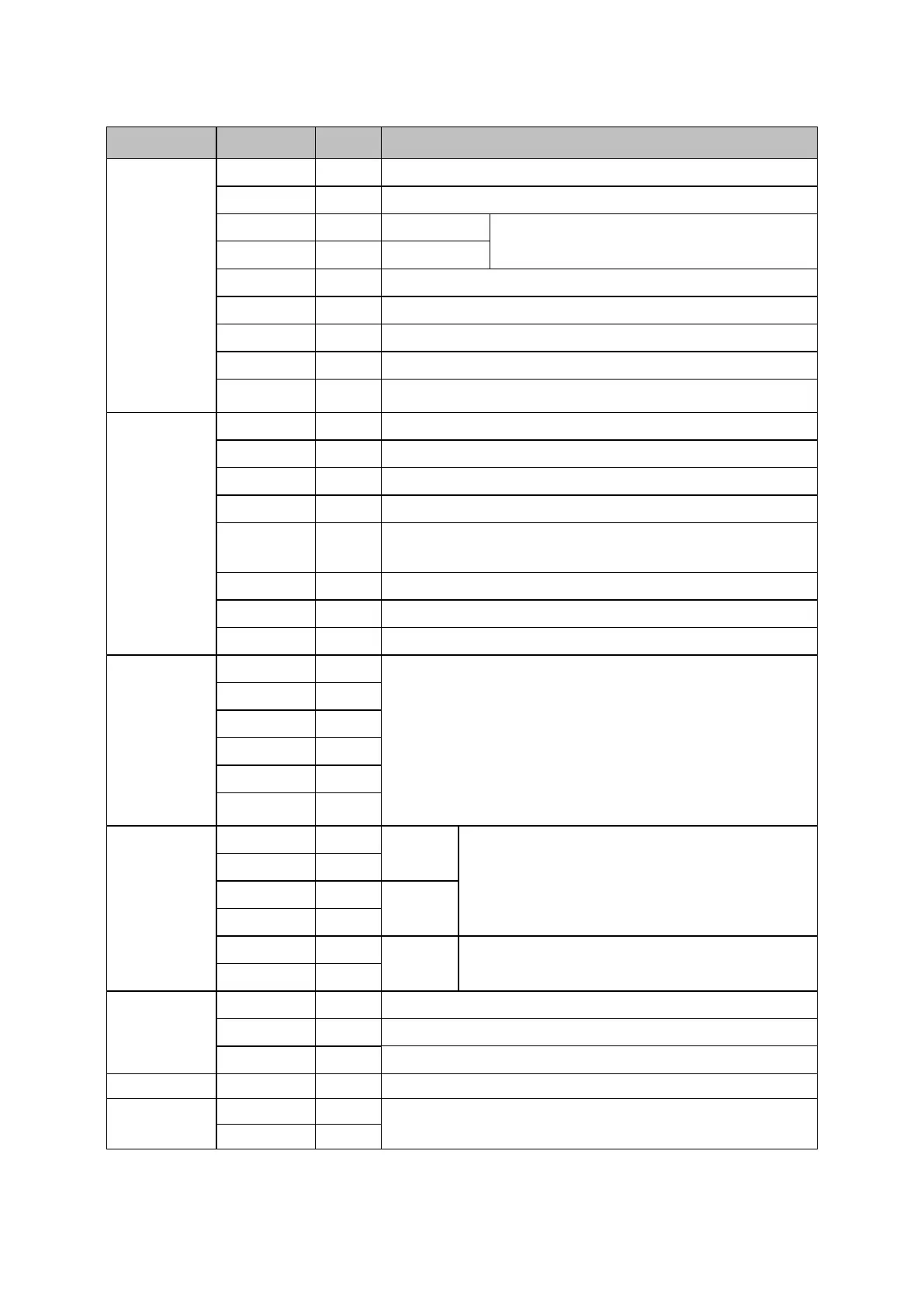
Signal of CN2 terminal
Servo ON: The motor is powered on.
Alarm clear: release servo alarms.
Over-travel prohibited: Stop operation of servo motor
when it is on.
Position deviation clearance input during position control.
Control mode switch: Switch of two control modes.
I/O signal electric power supply; user needs to provide 24VDC power
supply.
Servo alarm: OFF when abnormal state is detected.
Servo ready: ON before S-ON if there is no alarm.
Release holding brake output.
Z phase signal open collector output.
Positioning reached (in position control mode) ; speed reached (in speed
control mode) .
Output signal common grounding terminal.
Pulse command input channel:
Pulse command can have three different input forms and can be selected
using PA28.
0:Sign+pulse train
1:CCW+CW pulse train
2:A+B pulse train
For 24VDC, use PULS24+ & PULS-, SIGN24+ & SIGN-.
Encoder feedback pulse signal (A phase, B phase) and
divided by the driver for output. Dividing parameter is
PA25.
Origin pulse (Z phase) signal, pulse width can be widened
using PA30.
Speed command voltage input (±10VDC)
Torque command voltage input (±10VDC)
Analog signal output signal (0~10VDC)
RS485 communication terminal.
Notes: for I/O signals of unassigned pins, please refer to 3.2 CONTROL SIGNALS.
 Loading...