MAINTENANCE
LOCK-OUT & TAG-OUT INSTRUCTIONS
2-1
Before entering any part of the baler, be sure that all sources
of energy have been shut off, all potential hazards have been
eliminated, and the baler is locked-out, and tagged-out in
accordance with OSHA, and ANSI requirements. Before
servicing the hydraulic system or the inside of the bale cham-
ber, the platen must be properly supported as shown on the
next page. The specific lock-out, and tag-out instructions
may vary from company to company (i.e. multiple locks may
be required, or other machinery may need to be locked-out,
and tagged-out). The following instructions are provided as
minimum guidelines.
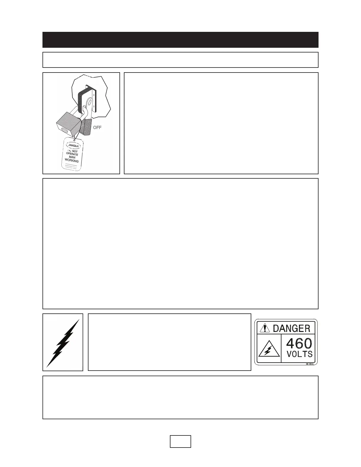
INSTRUCTIONS
1. Move the disconnect handle to the OFF position. The disconnect switch is located
in the panel box of the machine.
2. Padlock the disconnect handle with a keyed padlock, and take the key with you.
(To insert the lock through the lock tab on the disconnect handle, pull the lock tab out
of the disconnect handle when the handle is in the OFF position.)
3. Along with the padlock, place an appropriate, highly visible, warning tag on the dis-
connect lever. The tag should provide a warning such as: “ Danger: Do not operate
equipment. Person working on equipment.” or “ Warning: Do not energize without the
permission of ________________________.”
4. After locking, and tagging the baler, try to start, and operate the baler (as outlined
in the Operating Instructions) to make sure the lock-out and tag-out is effective. If the
lock-out and tag-out is effective, remove the key from the key switch, and take it with
you.
ELECTRICAL: The panel box contains high volt-
age components. Only authorized service person-
nel should be allowed inside the box. Authorized
service personnel should be allowed inside the
box only after the baler has been locked-out, and
tagged-out.
HYDRAULIC: Stored hydraulic energy must be removed from the baler hydraulic cir-
cuit for complete lock-out, and tag-out. Make sure that this energy has been relieved
by manually pressing the solenoid valve pin located in the center of the coil end of
each valve.
 Loading...