Do you have a question about the Dover OPW SiteSentinel Integra 100 and is the answer not in the manual?
Requirements for certified technicians to ensure safe installation of intrinsically safe devices.
Installation must comply with NEC and local codes for safe installation in hazardous areas.
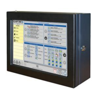
Details console dimensions, power, operating temperature, module capacity, and connectivity.
Guidance on power wiring, phase sharing, and routing wires through knockouts for the console.
Describes using twisted-pair wiring for Petro-Net communications between modules and the console.
Provides a visual guide for electrical connections for the Integra 100 console.
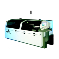
Provides a visual guide for electrical connections for the Integra 500 console.
Details wiring requirements for VSmart modules, including AC power and ground connections.
Explains how to assign unique identification numbers to VSmart modules using a rotary switch.
Wiring instructions for LIM modules, including AC power, ground, and noise suppressor installation.
Explains how to assign unique identification numbers to LIM modules using a rotary switch.
Important safety cautions regarding connecting the OM4 module and handling high voltages.
General wiring instructions for the OM4 module for Petro-Net communications and relay wiring.
Instructions for setting address jumpers on OM4 circuit boards when installing multiple modules.
Detailed steps for creating waterproof electrical connections using epoxy seal packs.
Procedures for sealing probe cables before entering the I.S. barrier to prevent explosive vapor entry.
Steps for installing probes in underground storage tanks, including manhole and junction box requirements.
Details the importance of correct probe sizing and the process for determining probe length.
Step-by-step instructions for measuring and calculating the required flex probe length for a specific tank.
Instructions for running data cables, handling extra cable length, and labeling connections.
Step-by-step guide for physically feeding and installing the flex probe into the tank opening.
Final steps for connecting the probe wiring, verifying operation, and waterproofing connections.
Safety and preparation steps before installing the VLLD sensor, including lockout/tagout.
Detailed steps for installing the VLLD sensor, including removing old detectors and applying thread sealant.
Instructions for connecting VLLD sensor wires in the junction box and sealing connections.
Steps for placing and connecting interstitial sensors, including routing and junction box use.
| Category | Industrial Equipment |
|---|---|
| Model | SiteSentinel Integra 100 |
| Manufacturer | Dover OPW |
| Display | LCD |
| Enclosure Rating | NEMA 4X |
| Certifications | UL, cUL, ATEX |
| Type | Automatic Tank Gauge (ATG) |
| Communication | RS-232, RS-485, Ethernet |
| Power Supply | 100-240 VAC, 50/60 Hz |
| Operating Temperature | -20°C to +50°C |