Doc. #: M1800, Rev. 06
Page 11 of 101
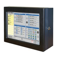
2.2 Console Specifications
2.3 Console Installation
To watch the instructional video for the installation of the Integra
console, simply use the following QR Code. Or, the instructional video
can also be found at www.YouTube.com by entering the search word
“OPWGlobal”.
Mount the console on the wall in a secure indoor location using the
mounting holes provided. If possible, align the console so the display
is easily visible and at a comfortable eye level at approximately 5 to
6 feet (1.5 to 1.9 m) above ground if mounted on a wall. Knockout
locations and cabinet dimensions are shown below.
NOTE: Any unused knockouts must be plugged.
Width: 15” (38.1 cm)
Height: 12” (30.5 cm)
Depth: 4” (10.0 cm)
120/240 VAC +/- 10%, 50/60 Hz, 200 W
32F to 122F (0C to 50C)
One (1) Internal I.S. Barrier (standard w/Integra™
100) with four (4) barrier positions
Optional Module
Capacity (only for
Integra 500):
Up to seven (7) optional VSmart Modules*
Up to four (4) optional Output Modules (OM4)
Up to four (4) optional Line Interface Modules (LIM)
15” (38.1 cm) color LCD touch-screen display GUI
One (1) Optional Internal Modem
Standard Alarms:
Optional Alarms:
Alarm Notification:
Buzzer; Light and Acknowledgement w/Blank Door
External Tank Alert (internal relay)
External OM4 module (only for Integra 500)
External LIM (only for Integra 500)
Email, Fax (with modem), SMS (with GSM modem)
Two (2) RS-232 Comm. ports
One (1) RS-485 Comm. port (only for Integra 500)
One (1) Ethernet port
Four (4) USB ports
Optional wireless communication between console
and VSmart (only for Integra 500)
DHCP/static addressable RJ-45 Ethernet ports,
supports corporate and local LANs
 Loading...