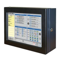
4.2 VSmart Module Installation
The VSmart module must be mounted on a wall using only the
mounting tabs provided. Module knockouts and mounting dimensions
are shown in drawings below.
Figure 4-2 VSmart Module Knockouts
Figure 4-3 VSmart Module Dimensions
4.2.1 Probe & Sensor Conduits
CAUTION: All installations must be carried out in accordance with
local regulations. Rigid steel conduit, which may or may not be
required, should be used whenever possible.
Each VSmart Module is equipped with eight (8) ¾-inch (19 mm)
knockouts to accommodate conduit for probe cables and sensor
wiring. Two (2) additional ½-inch (13 mm) knockouts are provided for
power and communication wiring conduits.
For probe and sensor field connections, always use a weatherproof
junction box.
4.2.2 Circuit Breaker Conduits
Run ½-inch (13 mm) conduit from the power knockout in the console
to the circuit breaker box. Run a corresponding ½-inch (13 mm)
conduit from the power knockout in each VSmart Module to the
circuit-breaker box.

 Loading...