8
System Layout
2.2 Rear Panel Layout
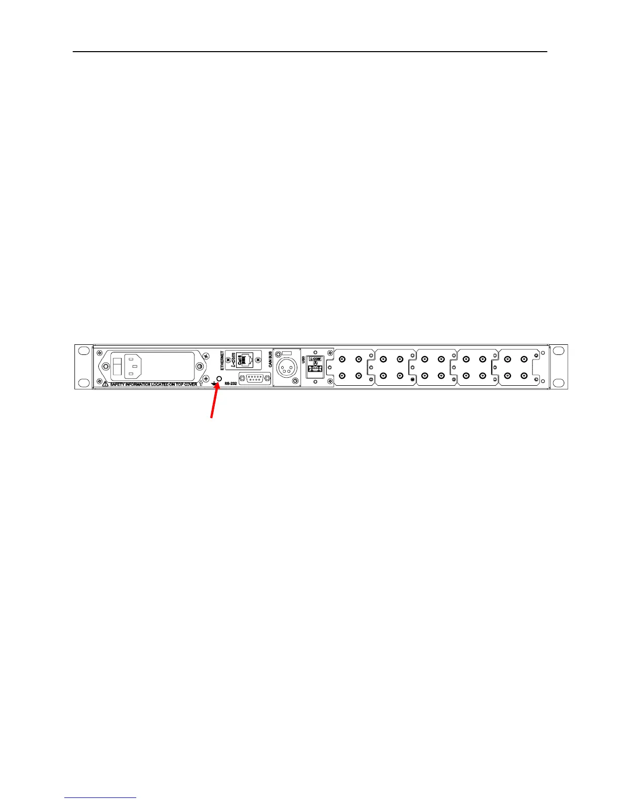
Figure 2-2 shows an example of a 1U model rear panel general layout. All
models have common parts which include:
• Power Entry Module with built in Fuse
• Chassis Ground Post
• 9-Pin D-Sub Female RS232 Connector
• 4-Pin XLR Female CAN Bus / 12V power (output) Connector
• RJ-45 Ethernet Connector
• USB type A Connector
Other parts that are not common to all models are Coaxial RF switches and/or
RF connectors.
GND stud
Figure 2-2, 1U MS series (with external switches) Rear Panel Layout
 Loading...