13
Connections
Pin 1 NC
Pin 2 Transmit
Pin 3 Receive
Pin 4 NC
Pin 5 Ground
Pin 6 NC
Pin 7 NC
Pin 8 NC
Pin 9 NC
Table 3-2, RS232 Female Connector Pin Functions
3.4 CAN Bus Connection
This connection allows the matrix controller to be easily interfaced to another
Dow-Key Microwave Switch Extension Matrix, using a one-to-one (straight
through) cable. However, the Matrix being interfaced must not have any
internal, intelligent controller; it must be a simple RF Switch Extension Matrix.
Furthermore, the switches in the extension matrix being interfaced must have
CAN ID’s unique to any others connected to the matrix. See Section 4 for more
information.
Care must also be taken to limit the internal power supply’s current draw on the
+12 VDC to a maximum of 7 Amps. Note that this includes all switches of the
master matrix and the extension matrix combined.
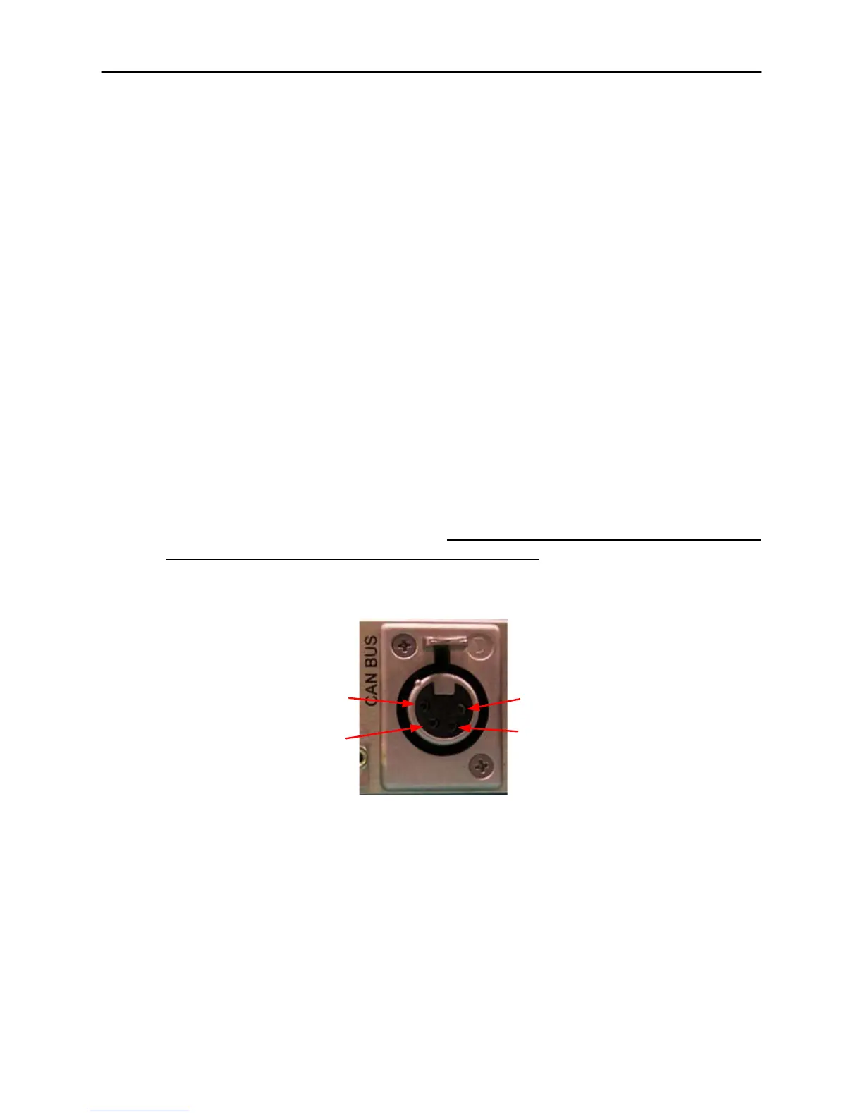
Figure 3-3 and Table 3-3 show the pin numbers and functions for the CAN Bus
connector.
1
2
3
4
Figure 3-3, CAN Bus Connector Pin Numbers
The mating connector is Deltron 701-0400. The pin outs (embossed on connector faces)
are:
1. +12 VDC, 7A max (this current is for master and extension matrices combined. See
Individual switch data sheets for current draw).
2. CAN LO
3. CAN HI
4. 12 VDC Return (GND)
Table 3-3, CAN Bus Connector Pin Functions
 Loading...