24
9.7 Hydro-Unit Level control
ID2962/29 052007
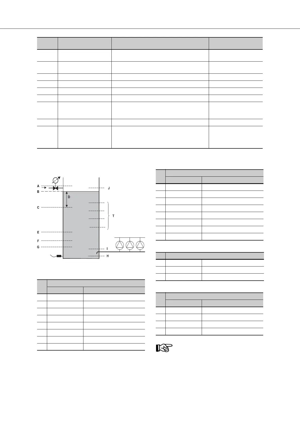
Figure 21: Megacontrol Level control
Table 23: Parameters supply valve ON/OFF
Table 24: Parameters supply valve prop.
Table 25: Parameters general.
Table 26: Parameters threshold
ATTENTION
Treshold 1/2 contacts are only available
with MCIII 6 pumps version by using
max. 4 pumps.
3-8-6-1 Digital Input 1 Function Configurable function of digital input 1 No Function
Control Digital Bit 0
3-8-6-2 Digital Input 2 Function Configurable function of digital input 2 No Function
Control Digital Bit 0
3-8-6-3 Digital Input 3 Function Configurable function of digital input 3 No Function
3-9-8-1 Flow Rate Estimation Activation of flow rate estimation 0=OFF
3-10-10-2 Upper Limit Defining the upper limit value for warning. When the
upper limit value is exceeded, a warning is triggered
after the time delay has lapsed.
3-10-10-1...3-11-8-2
50/60 Hz
4-1-1 Device ID User-defined device name for identifying the drive.
The control panel just allows read-only access to this
parameter. The device name can only be changed
via the ServiceTool/APP.
1 - 6
Para-
meter
Description Help text Factory setting
ID Parameter
3-4-1-4-9 Supply valve ON/OFF
A 3-4-1-4-7 High water level
B 3-4-1-4-9-2 Level 1 closed
3-4-1-4-9-4 Level 1A closed
C 3-4-1-4-9-1 Level 1 open
3-4-1-4-9-3 Level 1A open
E 3-4-1-4-6 Critical water level
F 3-4-1-4-5 Low level reset
G 3-4-1-4-4 Low level shutdown
ID Parameter
3-4-1-4-10 Supply valve prop.
A 3-4-1-4-7 High water level
3-4-1-4-10-1 Level setpoint 1
3-4-1-4-10-2 Level setpoint 1A
3-4-1-4-10-6 Open band
D 3-4-1-4-10-3 Hysteresis
E 3-4-1-4-6 Critical water level
F 3-4-1-4-5 Low level reset
G 3-4-1-4-4 Low level shutdown
ID Parameter
H 3-4-1-4-3 Sensor level
I 3-4-1-4-1 0% level
J 3-4-1-4-2 100% level
ID Parameter
3-4-1-4-8 Threshold
T 3-4-1-4-8-1 Threshold 1 ON
3-4-1-4-8-2 Threshold 1 OFF
3-4-1-4-8-3 Threshold 2 ON
3-4-1-4-8-4 Threshold 2 OFF
 Loading...