13
8 Operation
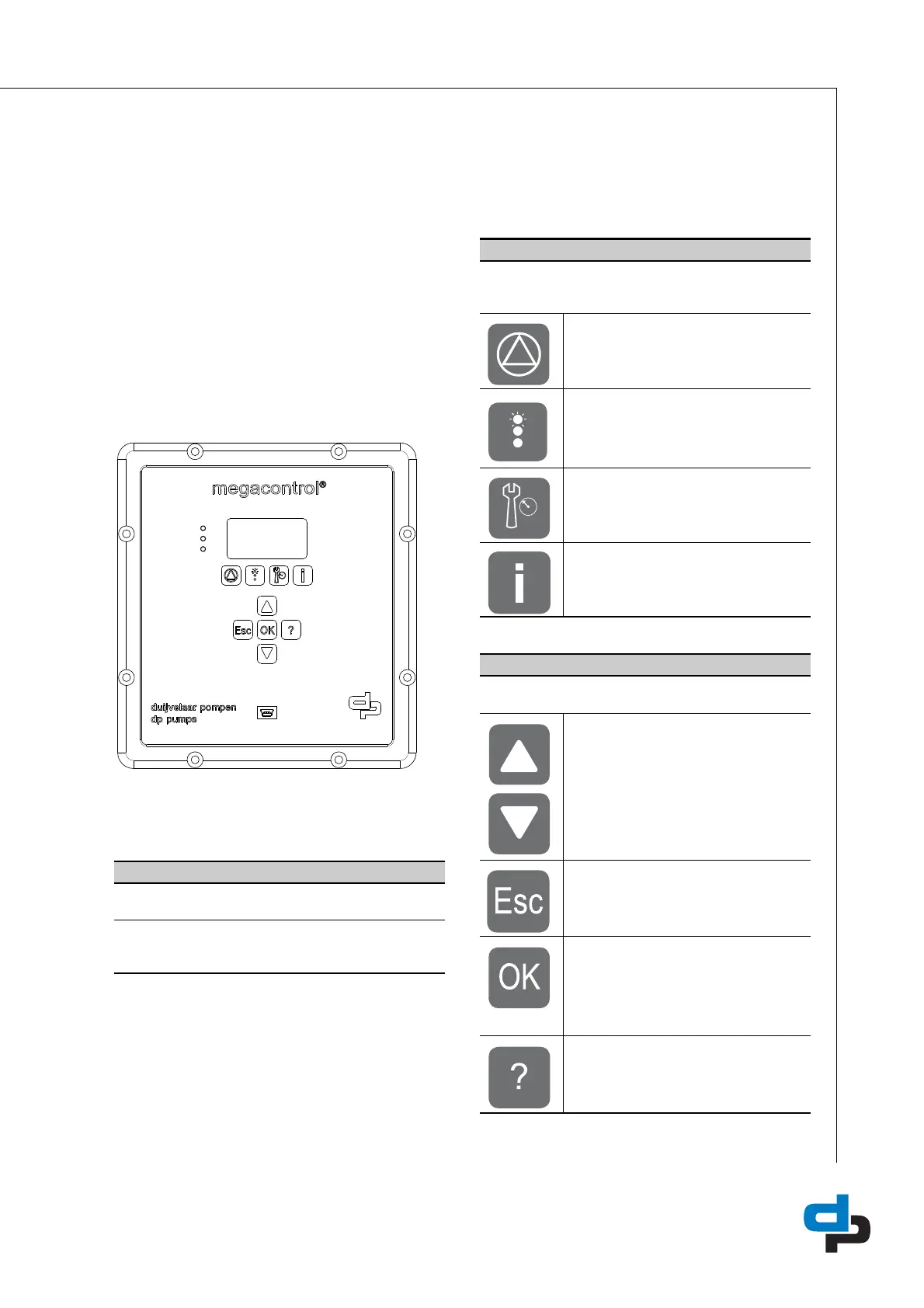
8.1 Control panel (HMI)
The control panel comprises a back-lit display,
function, navigation, and operating keys, LED’s, and
2 access points for the service interface. The display
shows important information for pump system
operation. Data can be displayed in plain text and
parameters can be set.
Table 10: Traffic lights
Table 11: Function keys
Table 12: Navigation keys
ID 2944
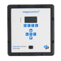
Figure 2: Front Megacontrol
20140253
A: LED’s
The “traffic light” signals provide information about the
pump system’s operating status. LED’s:
• Red: Alert / urgent alarm is active.
• Amber: Warning / non-urgent alarm is active.
• Green: O.K. / trouble-free operation.
B: Function keys
You can use the function keys to access the elements at
the first menu level directly: Operation, Diagnosis, Settings
and Information.
Operation
Diagnosis
Settings
Information
C: Navigation keys
The navigation keys are used for navigating in the menu
and for confirming settings.
Up or Down
• Move up / down through the root
menu (displays the measured values
of the system input);
• Move up / down through the menu
options or;
• Increase / decrease a value when you
are entering numerals.
Escape key
• Delete / reset entry (the entry is not
saved);
• Return to the previous menu level.
OK key
• Access to the quick menu;
• Confirm a setting;
• Confirm a menu selection.
• Go to the next number when you are
entering numerals.
Help key
• Displays a help text for each selected
menu option.
 Loading...