65
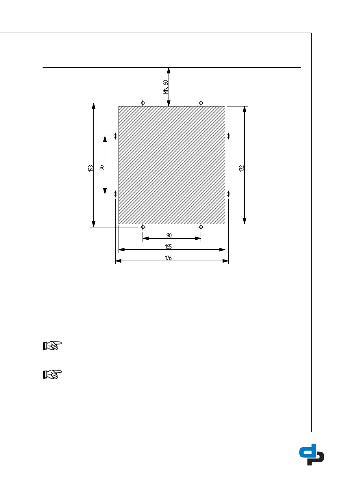
12.2 Built-in diagram
ID 2970/29052007
Figure 36: Built-in diagram
12.3 Electrical connections
Additional information on the RS485 bus: J302 to J301 and the use of a filter on the coil of contactors / auxiliary
relays. See chapter: 7.2.3 Using contactors
ATTENTION
Connections for bus communication (RS485 A/B) to frequency converter are moved from J302
to J301 (see drawing fig.: 37 Megacontrol Lay-out 1-3 (1-6) pumps)
ATTENTION
Changes to the DIP switch settings of the bus termination of the frequency converter becomes
only effective after switching off and then on again of the frequency converter.
 Loading...