67
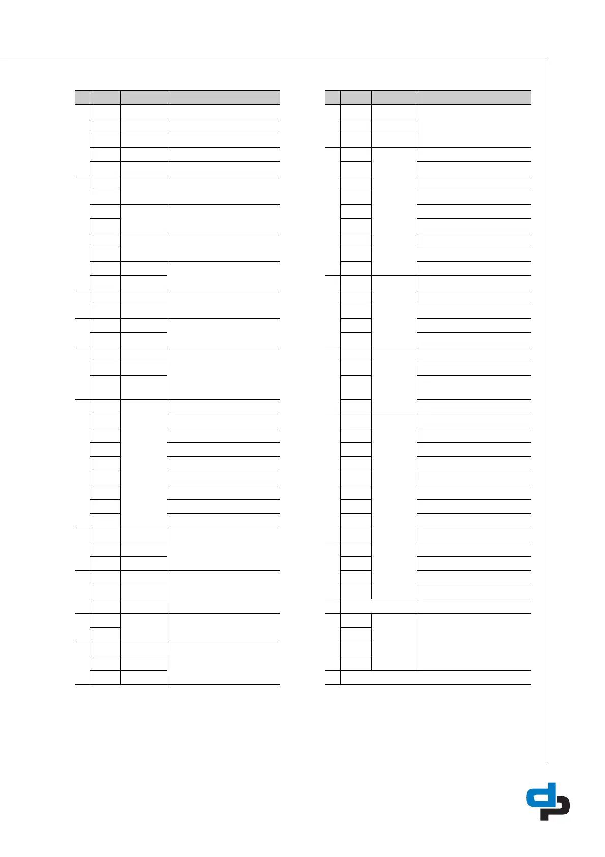
Table 49: Electrical connections
Nr: Code: Connection: Nr: Code: Connection
RS 485
1 T+ Termination resistor
J605B
41 NO Failure urgent
2 T- Termination resistor 42 COM
3B 43NC
4A
J602
44 Common
5 GND2 45 Common
J401
6
1
1. Connections 6 to 11 can be used for definable inputs
WSD sensor 1 46 Start VFD 1
7 47 Common
8 WSD sensor 2 48 Common
9 49 Start VFD 2
10 WSD sensor 3 50 Common
11 51 Common
12 + Temperature sensor 52 Start VFD 3
13 -
J601
53 Common
J502
14 + VFD 54 Start pump 1
15 - 55 Start pump 2
J501
16 + Valve (prop) 56 Start pump 3
17 - 57 Electric valve
J302
18 CAN L RS485
J102
58
2
2. Connections 58 up to 74 are only used with 4 to 6 pumps
Thermal failure pump 4
19 CAN M 59 Thermal failure pump 5
20 CAN
GND1
60 Thermal failure pump 6
J403
21 Thermal failure pump 1 61
3
3. Connections 61 to 74 can be used for definable outputs
Common
22 Thermal failure pump 2
J104
62 Common
23 Thermal failure pump 3 63 Common
24 Run-dry protection 64 Start VFD 4
25 Thermal failure VFD 65 Common
26 Thermal failure valve 66 Common
27 External stop 67 Start VFD 5
28 Fire alarm 68 Common
29 Common 24 V 69 Common
J405
30 24 V Suction 70 Start VFD 6
31 4-20 mA
J103
71 Common
32 GND 72 Start pump 4
J404
33 24 V Pressure 73 Start pump 5
34 4-20 mA 74 Start pump 6
35 GND
J604
36 Start / stop VFD
J201
L1 Power supply 230 Vac
37 L1
J605A
38 NO Failure not urgent N
39
4
4. Connections 39/40 and 42/43 are closed under normal use
COM PE
40 NC
 Loading...