17
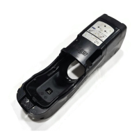
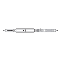
1 Insert the tube in the “Oil“ tube holder of the measring unit. The
arrow on the tube indicates the direction offlow (i.e. arrow must
point away from the measring unit).
Use only Dräger tubes
®
– see “Order List” on page 25.
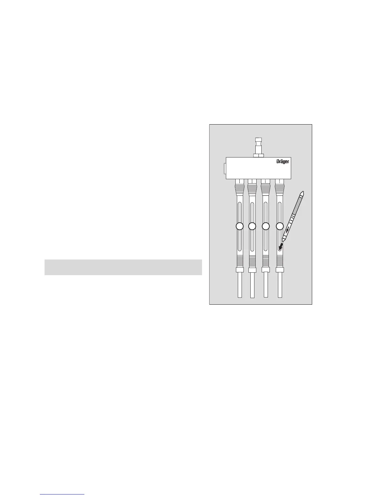
2 Break off both ends of the “Carbon dioxide 100/a-P“ tube and
insert it in the “CO
2
“ tube holder of the measuring unit.
3 Break off both ends of the “Carbon monoxide 5/a-P“ tube and
insert it in the “CO“ tube holder of the measuring unit.
The “Water vapour 20/a-P“ tube requires special handling:
● Break off the outlet end of the tube.
● Scratch-mark the inlet end of the tube with the tube opener, wit-
hout breaking it off.
● Slowly open the compressed air supply valve.
4 Insert the outlet end of the “Water vapour 20/a-P“ tube in the
“H
2
O“ tube holder of the measuring unit.
● Break off the inlet end in the air stream and simultaneously insert
it in the tube holder.
● Start the timer.
After the test time has elapsed:
● Close the compressed air supply valve. Remove the Dräger tubes
from the tube holder and evaluate the relevant levels with the aid
of the Instructions for Use of the Dräger tubes
®
.
Start by reading off the “Water vapour 20 /a-P“ tube.
NOTE
Do not inhale the gases released during measurement.
00521437.e
s
Oil CO H
2
OCO
2
1 2 3 4