Do you have a question about the Dräger REGARD and is the answer not in the manual?
Covers instructions, explosion hazards, liability, and maintenance requirements.
Intended use, description, power-on sequence, EMC.
Command mode, access, passwords, locking, master/modbus cards.
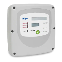
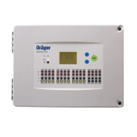
Details display, LEDs, and push buttons.
Describes faults, indicators, and fault code remedies.
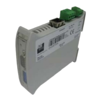
Installing input module, connecting RS-485, transmitters, and power.
Installing display card, connecting alarm relays and remote reset.
Accessing command mode, entering/changing passwords.
Saving, locking, quitting command mode, setting heads, gas names, units.
Setting measurement ranges, alarm trip levels, rising/falling alarms, latch modes.
Setting zero, span, drift band, fault levels, hysteresis, user text, display options.
Recommended intervals, daily checks, system maintenance tests.
Testing alarm relays, module communication, and disabling relays.
Technical data for display card and input module (voltage, temp, power, etc.).
Lists part numbers, CE/ATEX marking, and special safety conditions.
| Manufacturer | Dräger |
|---|---|
| Measurement Range | Varies depending on the sensor; refer to specific sensor specifications. |
| Resolution | Varies depending on the sensor; refer to specific sensor specifications. |
| Accuracy | Varies depending on the sensor; refer to specific sensor specifications. |
| Response Time | Varies depending on the sensor; refer to specific sensor specifications. |