15
Maintenance
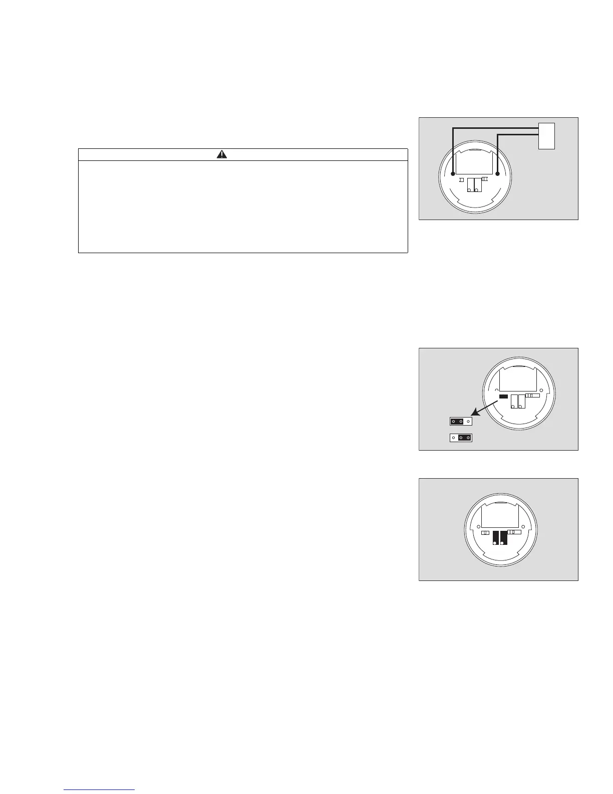
Output for calibration
4 Connect voltmeter (mV setting, Ri > 10 MΩ) to test points TP1 and TP2 (required
for the version without display).
— If a fault is detected, the voltmeter shows –200 mV.
— Voltage output –200 to 1100 mV:
–200 mV corresponds to a fault
–0 mV corresponds to zero concentration
–1000 mV corresponds to the 100 % measuring range end value
Jumper
5 Jumper J1 can be set to two positions.
6 The left-hand position or complete removal of jumper J1 in order to use the ma-
nufacturer's calibration setting for the sensor.
7 The right-hand position for calibration with calibration gas and the potentiome-
ters for zero point and sensitivity.
— Only the manufacturer's calibration setting for the sensor can be used when jum-
per J1 is set over the two left-hand pins.
— Calibration with calibration gas can be performed when jumper J1 has been set
over the two right-hand pins.
Operating elements
8 Potentiometer (left) for calibration of the zero point.
9 Potentiometer (right) for calibration of the sensitivity.
CAUTION
For operation in explosion-hazard areas:
Only use intrinsically safe voltmeters with electrical parameters to the following
specifications:
U
i
(V
max
) ≥ 7.6 V; I
i
(I
max
) ≥ 1 mA; U
o
(V
oc
) ≤ 10.4 V; C
i
≤ 2.5 µF; L
i
≤ 10 mH (C
o
(C
a
) and L
o
(L
a
) are not relevant as C
i
and L
i
of the test point circuit are zero)
MiniGrabber
©
Test Clips from Pomona Electronics (order no. 4723 or 4826) shall
be used for connecting the voltmeter.
The jumper J1 must be connected to the right-hand pin, when connecting the volt-
meter.
01523758_1.eps
+
–
TP1
TP2
4
mV
01623758_1.eps
6
7
J1
5
01723758_1.eps
89