Maintenance
16
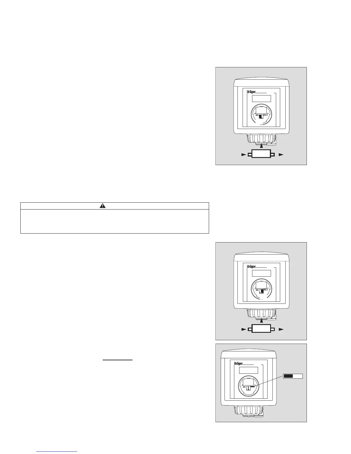
Calibrating the zero point
For all sensors except oxygen sensor:
The zero point can be calibrated without the use of nitrogen (zero gas) when the
ambient air is free from measuring gas and other interfering gases. Alternatively:
1 Use the calibration adapter.
Set maintenance switch to maintenance position, see page 14.
Let nitrogen flow through the calibration adapter at a rate of approx. 0.5 L/min.
Synthetic air may also be used, except when calibrating oxygen sensors.
Wait for the measured value to stabilise – approx. 3 minutes. Note the informa-
tion in the sensor data sheet.
2 Set potentiometer for zero point so that the display shows 0 and the digital volt-
meter 0 mV ±2 mV.
Oxygen sensors:
The zero point cannot be calibrated for these sensors. The zero point is merely
checked.
Switch off calibration gas and remove calibration adapter.
Set maintenance switch to measuring position, see page 14.
Calibrating the sensitivity
— The recommended calibration gas concentration for optimum accuracy is bet-
ween 40 % and 100 % of the measuring range end value.
1 Use the calibration adapter.
Set maintenance switch to maintenance position, see page 14.
Let calibration gas flow through the calibration adapter at a rate of approx. 0.5 L/
min.
— Wait for the measured value to stabilise – approx. 3 minutes. Note the informa-
tion in the sensor data sheet.
3 Set the potentiometer for sensitivity so that the display shows the concen-
tration of the calibration gas or the digital voltmeter shows the calculated
voltage mV.
Calculation of the voltage V
exp
between test points TP1 and TP2:
V
exp
= Concentration of calibration gas ÷ Measuring range x 1000 mV
Switch off calibration gas and remove calibration adapter.
Wait until the measured value drops below the alarm threshold set on the central
unit. Otherwise an alarm will be triggered when the maintenance switch is retur-
ned to the measuring position immediately after calibration.
1 Set maintenance switch to measuring position, left-hand position. The 4 to 20
mA output changes to measuring mode.
Refit the front cover of the service port and lock it in place by turning clockwise
with an Allen key (approx. 60
o
).
CAUTION
Test gas must not be inhaled. Risk to health!
Care must be taken about the risks which can arise when using test gas; hazard
instructions and safety advice must be observed.
For details, see appropriate Safety Data Sheets.
Example: Concentration of calibration gas 250 ppm CO
Measuring range 0 to 300 ppm CO
Calculated voltage: 250 ppm
V
exp
=
x 1000 mV = 833 mV
300 ppm