3367122 (A3-D-P) Page 2 of 5
Once stored, the information can be scrolled across the screen by pressing
the right button of the user interface (Fig B) during use.
The system is switched on by pressing the left and right buttons on the user
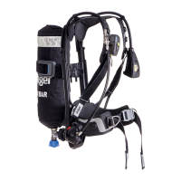
interface (Fig B), or by cylinder pressure detected at a pressure module in
the backplate, with pressure transmitted to the pressure module through a
high-pressure hose (Fig A, Item 3) when the cylinder is opened. At switch-
on, the unit performs a self-test (see Section 3.1.1), and once the self-test
is passed, the system adopts the active mode where the electronic
functions are operational.
The PASS alarm can be activated manually or automatically. The manual
alarm is activated by pressing the manual alarm button on the user
interface (Fig B, Item 2). The automatic alarm uses a motion sensor to
detect movement and activates a pre-alarm and main alarm at timed
intervals when no movement is sensed. The pre-alarm activates after 21-
25 seconds without movement, and the main alarm activates after
approximately a further 10 seconds without movement.
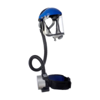
The HUD is fitted in the face mask to provide visual indications of system
conditions (see the HUD instructions for use for full details). Signals from
the Sentinel 7000 are transmitted to the HUD from a pressure transducer/
transmitter incorporated into the pressure module.
System power supplies are the main battery in the backplate, the backup
battery in the pressure module and the HUD battery in the HUD.
Dräger PC Link is an optional accessory that allows reading and
reprogramming of the Sentinel 7000. PC Link can reprogram settings and
parameters, including configuration, firmware and identification, and
download event record (datalog) information. Contact Dräger for full
details. The functions and parameters described in this document are the
default settings for the Sentinel 7000.
3.1.1 Sentinel 7000 start-up sequence and self-test
Each time the Sentinel 7000 switches on (with or without a compressed air
cylinder fitted), the Sentinel 7000 runs the self-test. During the self-test
sequence, the display scrolls through a series of screens and provides
start-up information and options, including:
● The main battery charge state.
● The electronic leak test option.
● The personal identity (scrolling data) option.
● If the system fails the self-test, the unit provides fail signal at the end
of the sequence.
The start-up sequence is:
1. The device emits a single tone from the user interface and the second
sounder, and the wait icon (Fig C) displays.
2. The tick icon (Fig D) displays and the blue, red, and green LEDs
illuminate.
3. The battery icon (Fig E) displays. The segments around the screen
indicate the condition of the main battery (all segments filled indicates
full battery).
4. The leak test icon (Fig F) displays. Pressing the left button (Fig B)
starts the optional electronic leak test procedure (see Section 4.6.5).
5. The personal identity icon (Fig G) displays. Pressing the left
button (Fig B) starts the procedure to read personal identity
information from a user ID card (see Section 4.6.6).
6. The automatic alarm icon (Fig H) displays and alarm tones sound.
7. End of sequence: the normal operating screen (Fig I) displays and the
green LED flashes at one second intervals.
3.1.2 Compressed air cylinders, lung demand valves, and face
masks
The PSS 7000 Series is compatible with composite material cylinders of 30
to 60 minute capacity, and is available in 2216 psi or 4500 psi versions.
Full descriptions and user instructions are contained in separate
instructions supplied with the cylinder, face mask, or lung demand valve.
3.2 Intended use
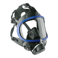
When the PSS 7000 Series is used with an approved lung demand valve,
face mask and compressed air cylinder, the breathing apparatus provides
a wearer with respiratory protection for working in contaminated or oxygen-
deficient conditions.
The compressed air cylinder, lung demand valve, face mask, and other
accessories used with this product must be certified Dräger components,
assembled in an approved configuration, otherwise the operation of the
device may be impaired. Contact Dräger for further information.
3.3 Limitations
A limitation of the PASS automatic distress alarm is that the motion sensor
detects movement or vibration to which the wearer is subjected, and may
not activate if the wearer is motionless on a moving platform (for example
on moving or vibrating machinery).
3.4 Approvals
The PSS 7000 Series is certified by NIOSH to 42 CFR Part 84. In certain
combinations, the series is certified by NIOSH to provide respiratory
protection from military grade chemical, biological, radiological, and
nuclear hazards (CBRN). The series is also certified by SEI to meet the
requirements of NFPA 1981:2018 and NFPA 1982:2018. The apparatus
must only be used with compressed air cylinders approved by NIOSH and
in an approved configuration (see Section 4.1).
This device (model: Sentinel 7000) complies with part 15 of the FCC
Rules. Operation is subject to the following 2 conditions: 1) this device may
not cause harmful interference, and 2) this device must accept any
interference received, including interference that may cause undesired
operation.
This device (model: Sentinel 7000) complies with RSS-310 of Industry
Canada. Operation is subject to the condition that this device does not
cause harmful interference.
3.5 Explanation of type-identifying marking and
symbols
NOTICE
The equipment may be damaged, or approvals invalidated, by engraving
it, or by applying chemical marking or paint.
► Do not use marker pens or apply paint, and do not scratch or engrave
the equipment.
► Dräger recommend using adhesive labels to add personal marking to
the equipment.
Refer to the relevant authority for explanation of approval body symbols
and marking on the equipment. Examples of other marking on component
parts of the breathing apparatus are:
4 Use
WARNING
Only trained and competent users are permitted to prepare and use this
equipment.
► Ensure that any accessories, ancillary equipment, and other
protective clothing items do not interfere with the breathing apparatus
and do not create a safety hazard.
The effective working duration of the apparatus depends on the initial air
supply available and the breathing rate of the wearer.
► Fill compressed air cylinders to their full rated pressure before use.
► Do not commence any operation (including supplied-air respirator
(SAR) operations) using a cylinder that is less than 90 percent full.
CAUTION
Equipment damage may cause the release of high-pressure air.
► Do not apply excessive force or use tools to open or close a cylinder
valve.
► Do not drop or throw down the breathing apparatus.
4.1 Prerequisites
Refer to the following additional information before preparing or using the
breathing apparatus:
● The special instructions (see Section 11).
● For non-CBRN use, see the separate NIOSH approval table 3367123
for approved configurations.
● For CBRN use, see the separate NIOSH CBRN approval table
3367124 for approved configurations. For CBRN use, the user must
also refer to the CBRN special instructions in the lung demand valve
instructions for use.
4.2 Preparation for use
Remove the thin flexible protective covering from the display before using
the device for the first time.
Replace the batteries if the device fails to operate, or if a low battery alarm
activates.
1. Carry out a visual inspection of the apparatus (see Section 4.6.1).
2. Install the main battery and the backup battery if necessary (see
Section 4.6.3).
3. Fit the compressed air cylinder (see Section 4.6.4).
4. Adjust the backplate height to the position required by the wearer (see
Section 4.6.2).
5. Press the male coupling of the lung demand valve hose into the female
coupling of the medium-pressure hose until an audible click is heard
(do not connect the valve to the face mask at this stage).
6. Press the reset button (Fig J, Item 1) to switch off the positive
pressure. Press and rotate the bypass button (Fig J, Item 3) to align
the red spots and then release the button to switch off the bypass.
7. Install the HUD into the face mask if necessary (see the HUD
instructions for use).
8. Carry out a full functional test of the apparatus (see Section 4.6.5).
9. Align and push the lung demand valve into face mask port until it
latches in position, and check the attachment by gently attempting to
pull the coupling apart.
4.3 Putting on the breathing apparatus
1. Fully loosen the shoulder harness and waist belt and put on the
breathing apparatus.
2. Check that the shoulder pads are not twisted and take the weight of the
system on the shoulders by pulling the shoulder harness. Do not fully
tighten at this stage.
3. Close the waist belt buckle and pull the ends of the waist belt forward
until the strap padding fits securely and comfortably over the
hips (Fig K). Tuck the belt ends behind the waist pad.
4. Pull the shoulder harness until the breathing apparatus rests securely
and comfortably on the hips. Do not over tighten. Pull the strap
retainers down to secure the strap ends (Fig L).
5. Fully loosen the head straps of the face mask and place the neck strap
over the back of the neck.
6. Press the reset button (Fig J, Item 1) to switch off the positive
pressure.
7. Open the cylinder valve (counterclockwise) slowly, but fully, to
pressurize system. The Sentinel 7000 and HUD systems activate.
● After storage at temperatures below 32 °F (0 °C) leakage may be
observed when the cylinder valve is initially opened due to ice
formation.
○ If leakage is observed from the lung demand valve, press the front
button (Fig J, Item 2) to allow a rush of air to pass through the lung
demand valve and then quickly press the reset button (Fig J,
Item 1) to switch off the positive pressure. Resume normal
operation.
○ If leakage is observed from the quick connect coupling, close the
cylinder valve and vent the system. Disconnect then reconnect the
cylinder to the breathing apparatus (see the quick connect
coupling instructions for use), then reopen the cylinder valve
slowly, but fully, to pressurize the system. Resume normal
operation.
BRAC-1359 – Dräger serial number
08/09 – Month and year of manufacture
3356812 or R21034 – Dräger part number
SF – Standard force coupling
LF – Low force coupling
○ If leakage still occurs, remove the breathing apparatus from
service and report the fault to trained service personnel or contact
Dräger.
WARNING
If there is not a good seal between the mask and the face of the wearer,
the mask may leak inward or outward during use.
► In a CBRN environment, use only face mask sizes that have been
confirmed by a quantitative fit test (QNFT).
8. Put on the face mask and check the seal between the mask and face
of the wearer (for non-CBRN use see the Dräger FPS
®
7000 face
mask instructions for use; for CBRN use see the CBRN special
instructions in the lung demand valve instructions for use).
4.4 During use
WARNING
Users should be in a safe area before the whistle or end-of-service-time
warnings commence.
► Fully open all cylinder valves and ensure that they remain open during
use.
► Evacuate to a safe area immediately if warnings commence during an
operation.
● Regularly check the user interface display to confirm the exact cylinder
pressure and the remaining time until to the end-of-service time
(EOSTI) alarm activates (see Section 10 for the EOSTI activation
pressures). Both are shown numerically on the normal operating
screen (Fig I). Cylinder pressure is also shown as follows:
○ The HUD LEDs show the approximate cylinder pressure (see
Section 4.4.1).
○ The segments on the user interface screen show the approximate
cylinder pressure (Fig I).
● To call for emergency help or assistance, press the manual alarm
button in the center of the user interface (Fig B, Item 2) to activate the
manual alarm.
● To illuminate the display backlight, press and release the left or right
button of the user interface (Fig B).
○ Pressing the right button (Fig B) displays any programmed
personal identity information (see Section 3.1).
● React to the following alarm and warning signals as necessary:
○ EOSTI – The user interface emits an audible alarm tone, and red
and blue LEDs flash and part of the display flashes red. The red
LED (Fig M, Item 1) on the HUD flashes. The mechanical whistle
on the first-stage regulator sounds.
○ PASS pre-alarm – If no movement is detected for 21-25 seconds,
a repeating audible alarm tone is emitted from the user interface
and the second sounder. Move the user interface within
10 seconds to cancel the alarm (do not attempt to use the buttons
to switch off the pre-alarm).
○ PASS main alarm – If no movement is detected after
approximately 10 seconds of pre-alarm, a high-level sweeping
alarm is emitted from the user interface and the second sounder.
Red and blue LEDs on the user interface and the top and bottom
of the second sounder flash intermittently. The user interface
displays the automatic alarm icon ( ). To cancel the alarm,
simultaneously press and hold the left and right buttons of the user
interface (Fig B) until the alarm stops.
○ Low main battery – A low battery icon displays on the user
interface (Fig N), and the battery LED (Fig M, Item 5) on the HUD
flashes yellow.
○ Low HUD battery – The battery LED (Fig M, Item 5) flashes green.
○ Loss of HUD communication – The blue communication LED
(Fig M, Item 4) flashes.
WARNING
Using the bypass button (Fig J, Item 3) uses air from the cylinder and may
rapidly reduce the working duration of the apparatus.
► Do not use the bypass button unless absolutely necessary.
● If additional air is required, briefly press and release the bypass
button (Fig J, Item 3) to deliver a single jet of air into the face mask.
WARNING
The following emergency air flow procedures may greatly reduce the
operating duration of the air supply.
► When activated the user must immediately evacuate to a safe area.
► The reason for using the procedure must be investigated and repaired
before reusing the breathing apparatus.
● Additional air flow required (emergency procedure only used in the
unlikely condition of low or blocked airflow) – Press and rotate the
bypass button (Fig J, Item 3) to deliver a sustained air supply (85 to
130 liters/minute) into the face mask.
● Excessive or loss of air flow (emergency procedure only used in the
unlikely condition of high or loss of airflow) – Close the cylinder valve
then immediately begin to slowly reopen the valve. Use the cylinder
valve as a regulating valve to set the air flow to meet the user
requirement. This procedure can be used with screw-type and ratchet-
type cylinder valves.
4.4.1 HUD LEDs
The LEDs, red (Fig M, Item 1), amber (2), and two green (3), indicate the
cylinder pressure range and provide alert signals at critical pressures. The
following table shows the cylinder pressures indicated by the LEDs.
Table key: ● –On
* – Flashing
Approximate cylinder pressure
LED
Red Amber Green Green
100 % to 75 % ●●●●
75 % to 50 % ●●●
50% content alert (amber flashes for
20 seconds)
● *
50 % to 35 % ●●
35 % to 100 psi (red flashes
continuously)
*
Below 100 psi HUD logs off
 Loading...