26
INSTALLATION MANUAL
6.3 Gas connection
Place a gas tap in the gas connection, close to the appliance.
- Make sure there is no dirt in gas pipes and
connections;
- Prevent twisting the gas tap when con-
necting the gas pipe.
The following requirements apply to the gas connection:
- use a gas pipe with the correct dimensions, so that no
pressure loss can occur;
- the gas tap should have the CE marking;
- you should always be able to reach the gas tap.
6.4 Placing the appliance
For construction in a mantelpiece/fi replace connected
to an existing chimney – only allowed in Great-Britain –
the instructions from the separate booklet ‘Fitting into a
conventional class 1 chimney’ also apply. In addition to the
installation instructions, this booklet also contains supple-
mentary tests.
- Make sure that combustible objects and/or
materials have a distance from the
appliance of at least 500 mm;
- Always place the appliance against a wall of
non combustible and heat-resistant
material;
- Maintain a minimum distance of 10 mm
between the appliance and the back wall;
- Take suffi cient measures to prevent tempe-
ratures of a wall behind the chimney breast
becoming too high, including the materials
and/or objects behind the wall;
- Place the appliance on supports made of
non combustible and heat-resistant
material;
- Do not cover the appliance and/or do
not wrap it in an insulation blanket or any
other material;
- Do not make any changes to the appliance.
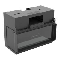
!Caution - Take the minimum construction depth of
the appliance into account;
Global 40 CF 300 mm (see fi g. 2);
The appliance must be built tightly in the chimney breast
(frameless) or provided with a decorative strip or front all
around it. Upon request, the plaster strip, the front or front
will be included in the delivery.
Place the appliance as follows:
• Apply the plaster strip, in case of a tight construction of
the appliance; also see the instructions included with the
delivery.
• Determine the location of the appliance; see fi g. 1 for the
dimensions of the appliance.
• Determine the construction height of the appliance.
• Provide a gas connection at the location. For details, see
section 6.3.
• Make a passage for the fl ue gas discharge system with the
following diameters. For details, see section 6.5.
- Ø90 mm for a roof terminal through non combustible
material;
- Ø 180 mm for a roof terminal through combustible mate-
rial.
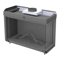
• Place the appliance - on its intended location - on the
required height (see fi g. 3) and
• Make the appliance level at the same time.
• Connect the gas pipe to the appliance, as described below.
The gas control is located below the burner. In order to
connect the gas pipe, you must remove the burner mounting
plate.
Follow the procedure described below:
• Remove the glass pane (see section 6.8)
• Store the glass pane on a safe place
• Unscrew the two self-tapping screws under the combus-
tion chamber and remove this cover (see fi g. 4a)
• Remove the vermiculite tray (see fi g. 4b)
• Unscrew the 4 self-tapping screws of the burner mounting
plate and remove the burner mounting plate plus accesso-
ries (see fi g. 4c)
• Unscrew the Allen screws (4x) at both sides of the com-
bustion chamber using the supplied Allen key (see fi g. 4d)
• Take hold of the combustion chamber at both sides and
remove it (see fi g. 4e)
• Provide a gas supply into the convection box (see fi g. 4f)
• Attach the convection box to the wall using the key bolts
and washers supplied (see fi g. 4g)
• If necessary, blow clean the gas pipe.
• Place the combustion chamber back in the convection box
and fi x it at both sides with the Allen screws.
• Connect the fl exible gas pipe to the gas connection with
gas tap.
- Avoid kinks in the pipe;
!Caution Properly connect the fl ue spigot to the
draft interrupter when placing back the
combustion chamber (see fi g. 4h)
• Bleed the gas pipe.
• Place the receiver; for details, see section 7.1 of the
Installation manual.
• Set the communication code between the remote control
and the receiver; see section 7.2 of the installation manual.
Do not ignite the appliance until it is fully
installed.
• Check the connections for gastightness as described in
section 8.1 of the installation manual.
• Check the line-pressure as described in section 8.2 of the
installation manual.
Caution
Caution
Caution
Caution