26
INSTALLATION MANUAL
the left side of the appliance. It should remain connected to
the chain.
Check whether the appliance is suitable for
the type of gas and the gas pressure used at
the location.
6.3 Gas connection
Place a gas tap in the gas connection, close to the appliance.
- Make sure there is no dirt in gas pipes and
connections;
- Prevent twisting the gas tap when con-
necting the gas pipe.
The following requirements apply to the gas connection:
- use a gas pipe with the correct dimensions, so that no
pressure loss can occur;
- the gas tap should have the CE marking;
- you should always be able to reach the gas tap.
6.4 Placing the appliance
When constructed in an existing chimney (other than the
class 1 chimney in the United Kingdom), a exible stainless
steel pipe is recommended for discharging the ue gases.
In cases of construction in a mantelpiece/ replace connec-
ted to an existing chimney in the United Kingdom (class 1
chimney), the separately supplied English description ‘Fitting
into a conventional class 1 chimney’ also applies. In addition
to the installation instructions, this booklet also contains
supplementary tests. In the United Kingdom, the ‘Concise
installation guide’ also applies.
- Make sure that combustible objects and/or
materials have a distance from the
appliance of at least 500 mm;
- Always place the appliance against a wall of
non combustible and heat-resistant
material;
- Maintain a minimum distance of 10 mm
between the appliance and the back wall;
- Take suf cient measures to prevent tempe-
ratures of a wall behind the chimney breast
becoming too high, including the materials
and/or objects behind the wall;
- Place the appliance on supports made of
non combustible and heat-resistant
material;
- Do not cover the appliance and/or do
not wrap it in an insulation blanket or any
other material;
- Do not make any changes to the appliance.
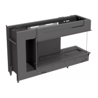
!Caution - Take the minimum construction depth of
the appliance into account;
Global 70XT CF 350 mm (see g. 2);
- Take the minimum construction height of
the appliance into account: 180 mm
(see g. 2)
The appliance must be built tightly in the chimney breast
(frameless) or provided with a decorative strip or front all
around it. Upon request, the plaster strip, decorative strip or
front will be included in the delivery.
Place the appliance as follows:
• Apply the plaster strip, in case of a tight construction of
the appliance; also see the instructions included with the
delivery.
• Determine the location of the appliance; see g. 1 for the
dimensions of the appliance.
• Determine the construction height of the appliance.
• Provide a gas connection at the location. For details, see
section 6.3.
• Make a passage for the ue gas discharge system with the
following diameters. For details, see section 6.5.
- Ø110 mm for a roof terminal through non combustible
material;
- Ø 200 mm for a roof terminal through combustible mate-
rial.
• Place the appliance - on its intended location - on supports
with the required height (see g. 3) and
• Make the appliance level at the same time.
• Connect the gas pipe to the appliance, as described below.
The gas control can be found in the tray below the burner.
In order to connect the gas pipe, you must remove the bur-
ner mounting plate.
Follow the procedure described below:
• Remove the glass pane (see section 6.8).
• Store the glass pane on a safe place.
• Remove the vermiculite tray (see g. 4a)
• Unscrew the Allen screws at both sides of the combustion
chamber using the supplied Allen key (see g. 4b).
•
Grab the combustion chamber at both sides and remove it
(see g. 4c).
• Remove the bottom strip (see g. 4a)
• Unscrew the self-tapping screws of the burner mounting
plate; see g. 4d.
• Lift the burner mounting plate plus accessories; see g. 4e.
• Attach the convection box to the wall, using the supplied
key bolts and at washers. Use the 4 openings in the rear
wall of the convection box.
• Cut the inner ring out of the left or the right sided grom-
met. The grommet is placed in the bottem of the tray
below the burner.
• Create a gas supply leading into the tray, under the burner.
(see g. 4h)
• If necessary, blow clean the gas pipe.
• Connect the exible gas pipe to the gas connection with
gas tap.
- Avoid kinks in the pipe;
!Caution The pilot burner pipe must be protected
against possible corrosion in uences, e.g.
moisture, falling cement, dirt falling down
from a chimney, etc. The pilot burner pipe
Caution
Caution
Caution
Caution