28
INSTALLATION MANUAL
- Make sure that the appliance is not car-
rying the weight of the chimney breast
when using stone-like materials;
- The ventilation holes – which should be
mounted as high as possible – should have
a combined passage of at least 200 cm
2
.
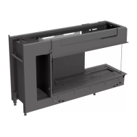
!Caution - Take the minimum internal width of the
chimney breast into account: 750 mm
(see g. 2);
- When placing the chimney breast, you
should take the location of the ventilation
holes (V) into account (see g. 2).
!Tip You should preferably apply the ventila-
tion holes on both sides of the chimney
breast. You can use DRU ventilation
elements.
• Check whether the ue gas discharge system is placed
correctly.
• Check the xture of the clip binding with self-tapping
screws on places that cannot be reached later on.
• Do not apply plaster on or over the anges (see g. 2,
maximum plaster line M), because the heat of the appli-
ance could cause cracks.
• If necessary, place the decorative strip or front around
the appliance; also see the instructions included with the
delivery.
• When using stone-like materials and/or plaster nishing,
the chimney breast should dry for at least 6 weeks before
it is taken into operation, in order to prevent cracks.
6.7 Placing the wood set
The appliance is supplied with a wood set.
Strictly observe the following instructions
to prevent unsafe situations:
- only ever use the supplied wood set;
- place the wood set exactly as described;
- make sure the pilot burner and the space
around it are kept free from objects (see
g. 5a);
- make sure thermocouple 2 and the sur-
rounding space remain free (see g. 5a)
- make sure there is no vermiculite’s ne
dust on the burner.
6.7.1 Wood set
The wood set consists of black vermiculite (see g. 6a),
chips (see g. 6b) and four logs.
• Fill the burner tray with vermiculite; equally spread the
vermiculite.
!Caution - You can in uence the ame image by
moving the vermiculite, yet
- the burner deck has to remain covered
with vermiculite in order to prevent that
the life expectancy of the burner is
reduced.
• Identify logs A up to D by using g. 7a.
!Tip Use the burn stains on the logs for identi-
cation.
• Successively place log A (rear log), log B (middle log) and
log C (right log); see g. 7b to 7h.
!Caution Use the placement brackets as indicated
in the gures.
• Fill the tray surrounding the burner with chips; equally
spread the chips; see g. 7j.
• Finally place log D, the left log; see g. 7k.
6.8 Glass pane
After placing the wood/pebble set you can place the glass
pane, as described below.
!Caution - Avoid damages when removing/placing
the glass pane;
- Use the Allen key supplied for loosening/
tightening the Allen screws.
6.8.1 Removing the glass pane
Remove the glass pane in accordance with the following
instructions (zie g. 10a up to g. 10d)
• Loosen the Allen screws in the upper glass strip by one or
two strokes.
• Grab the upper glass strip at both sides.
• Pull the glass strip to the front and
• Push it upwards.
• Slightly tilt the top of the glass pane towards you.
• Grab the glass pane at both sides.
• Remove the glass pane from the lower glass strip.
6.8.2 Placing the glass pane
• Place the glass pane in the lower glass strip.
• Pull the upper glass strip to the front and
• Push it upwards.
• Tilt the top of the glass pane away from you.
• Place the upper glass strip over the glass pane.
• Push on the upper glass strip.
• Retighten the Allen screws
!Caution
- Avoid/remove ngerprints on the pane,
since otherwise they will burn into the
surface;
- The Allen screws must not be over-
tightened, since otherwise they could
strip the thread: tight=tight;
7. Wireless remote control
The appliance is supplied with a wireless remote control.
Ignition, controlling the ame height and switching off are
performed by a remote control that operates a receiver.
User Manual, chapter 4, Wireless Remote Control, des-
cribes the operation of the appliance including the way the
remote control works.
Caution
 Loading...