EasyManuals Logo

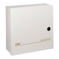
DSC MAXSYS PC4020 System Manual

DSC MAXSYS PC4020
36 pages
To Next Page IconTo Next Page
To Previous Page IconTo Previous Page
Page #30 background imageLoading...
Page #30 background image
List of Diagnostics
Indicated PC4400 Serial
Number Interface Module
25 1
Indicated PC41XX Zone
Number Module
26 1
27 2
28 3
29 4
30 5
31 6
32 7
33 8
34 9
35 10
36 11
37 12
38 13
39 14
40 For future use15
41 For future use16
Indicated PC4216
Number O/P Module
42 1
43 2
44 3
45 4
46 5
47 6
48 7
49 8
50 9
Indicated PC4204
Number O/P Module
51 1
52 2
53 3
54 4
55 5
56 6
57 7
58 8
59 9
60 10
61 11
62 12
63 13
64 14
65 15
66 16
Indicated PC4700
Number Fire Module
67 1
Indicated Escort4580 Voice
Number Prompting Module
68 1
E = Communication error
T = Tamper open
LV = Low voltage to module
Indicated # For Future Use
Number
1
2
3
4
5
6
7
8
Indicated LCD4500
Number Module
91
10 2
11 3
12 4
13 5
14 6
15 7
16 8
17 9
18 10
19 11
20 12
21 13
22 14
23 15
24 16
APPENDIX B

Other manuals for DSC MAXSYS PC4020

Questions and Answers:

Question and Answer IconNeed help?

Do you have a question about the DSC MAXSYS PC4020 and is the answer not in the manual?

DSC MAXSYS PC4020 Specifications

General IconGeneral
Partitions8
Event Buffer1000 events
Keypads16
Power Supply16.5V, 40VA transformer
Battery Backup12V 7Ah (typical)

Related product manuals