6
leads (of the module); the output voltage should be 13.85
V. If the voltage is good then check the battery (under
load), even if the battery is under a load the voltage
should still be above 12.0 V. Once all (if any) battery
troubles have been taken care of, be sure that there are
no Combus Low Voltage troubles. If there are locate the
modules with the low voltage troubles by entering
Installers Mode and selecting Diagnostics. Refer to
Appendix B for the List of Diagnostics. Once the
module(s) have been isolated a PC4204 will be required
to increase the power to be module with the low voltage
trouble. Now that all trouble have been taken care of the
next step is to remove AC power from all modules and
allow the panel to run for 10 - 15 minutes on battery power
alone. If there are any Combus Low Voltage troubles a
PC4204 Combus repower module may be required at the
Low voltage location to insure proper system operation.
Repeat this test as required.
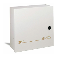
Mounting the Panel
Select a dry location close to an unswitched AC source, a
ground connection and a telephone connection for
mounting the Main Control Cabinet.
Remove the PC4020 printed circuit board, mounting
hardware, and keypad from the cardboard retainer inside
the large cabinet. Before attaching the cabinet to the wall,
press the five white nylon printed circuit board mounting
studs into the cabinet from the back.
Pull all cables into the cabinet and prepare them for
connection before mounting the circuit board to the back
of the cabinet. Press the circuit board down onto the
mounting studs.
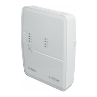
There is room in the Main Control Cabinet (PC4001C) for
any two modules (PC4108, PC4116, PC4216 or PC4400).
Modules requiring power (AC and battery PC4204) must
be installed in the large Expander Cabinet (PC4002C).
This enclosure will accommodate one module (PC4108,
PC4116, PC4216 or PC4400) and a powered output
(PC4204) or any three modules. A small Expander Cabinet
(PC4003C) is available for a single module that does not
require external power.
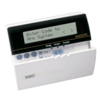
Once the wiring is completed power the system up by first
connecting the battery followed by the AC transformer. All
LCD4500 keypads should display the message ‘LCD4500
DSC Ltd.’. Press a key on any keypad that is to be
assigned to Partition 1. The keypad will beep and display
the message ‘4500 Mod. #1' and the keypad is
automatically assigned to Partition 1.
Enroll every module to the system. Make sure you put
down the number of each module enrolled. Refer to the
Programming Manual for the required procedure.
When enrolling any PC4108 or PC4116 zone expander
module make sure to note the zones which you assigned
to the module.
This information is very important if it becomes necessary
to Add or Delete zones to or from a Partition. Zones 1
through 16 are assigned to Partition 1 by default. This can
be changed later in Installer Programming.
In Book 4 (Programming Work Sheets) you will find a
System Overview section. Fill in the information as each
module is enrolled. These sheets are designed to be left
in the panel so if future service is required, the location
and assigned number of each module will be readily
available.
Once all modules are enrolled perform a diagnostics
check on the panel to determine if any problems are
present (see “Diagnostics”).
Programming the System
The PC4020 has the capability to operate as 8 separate
alarm systems called Partitions. Dividing the panel into
Partitions will allow you to control access to specific
areas.
When the PC4020 is first powered up all zones on the
main board and User Codes are assigned to Partition 1. If
no other Partitions are required the entire system will be
considered Partition 1. This is important to keep in mind
as often in programming the panel will require you to enter
the Partition to program.
For example, when programming entry and exit times, you
must select the menu option ‘ADD/EDIT PAR’. The keypad
will then prompt you for the Partition to add or edit. You
must select Partition 1 for a system that has no additional
Partitions.
The factory default setting for all options is provided in the
Programming Work Sheets as well as programming
‘HOTKEYS’ for the option to allow quick programming.
Complete the Programming Work Sheets located in Book
4. Having this information prepared before programming
the panel will speed up the process considerably.
All information for the panel may be entered in the
Programming Work Sheets.
Any zone expanders on the system will include a similar
sheet and the information should be completed for
these as well.
There is no set order in which the panel must be
programmed, however, if you use the following guideline it
may simplify the programming of the panel for the first time.
Step 1 - Define all Partitions
When the panel is first powered up the 16 zones on the
main panel are assigned to Partition 1. Additional zone
expanders enrolled to the system are NOT assigned to
any Partition.