PowerSeries - PC1616/PC1832/PC1864
4
1.5 AUX Power Wiring
The control panel can provide a maximum of 700mA of current for modules, powered detectors, relays, LED’s etc. If the total
current required exceeds 700mA an additional power supply is required (e.g.,PC5200, PC5204). See list below.
Min/max operating voltages for devices, sensors and modules is 9.5V
DC - 14VDC
Refer to the list of Compatible Devices on page 1 and/or the Reference Manual for the current draw of individual devices
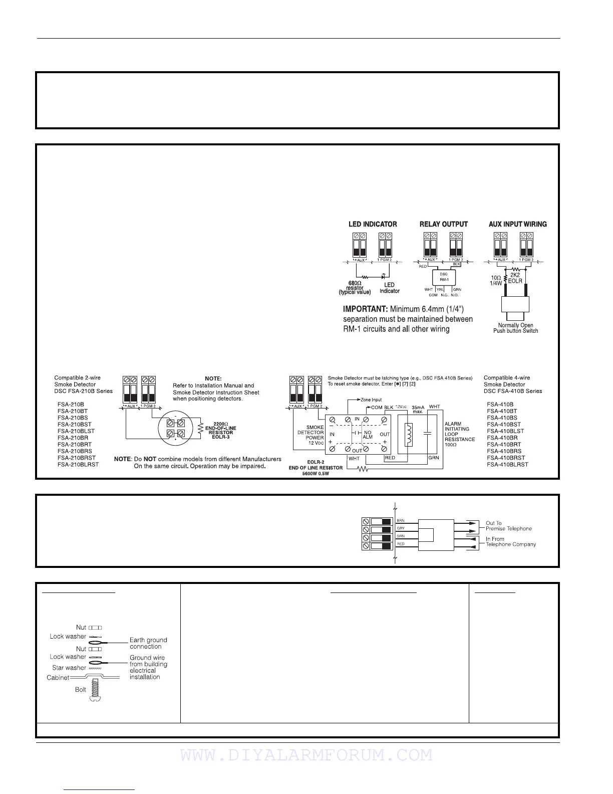
1.6 PGM Wiring
PGMs switch to ground when activated by control panel.
Connect the positive side of the device to be activated to the AUX+
Terminal. Connect the negative terminal to the PGM.
current output is as follows
• PGM 1, 3, 4............................................................................... 50mA
• PGM 2..................................................................................... 300mA
For currents levels greater than 300mA a relay is
required. PGM2 can also be used for 2-wire smoke
detectors.
NOTE: Use SEOL resistors on Fire Zones ONLY.
PGM 1, LED output with current limiting resistor and
Optional Relay driver output
2-wire Smoke Detectors Initiating Circuit
• Style B (Class B), Supervised, Power Limited
• UL Compatibility Identifier....................................................PC18-1
• DC Output Voltage........................................................9.8-13.8 VDC
• Detector Load ............................................................... 2mA (MAX)
• Single-end-of-line (SEOL) Resistor ........................................ 2200Ω
• Loop Resistance.............................................................. 24Ω (MAX)
• Standby Impedance..................................................... 1020Ω (ΝΟΜ)
• Alarm Impedance.......................................................... 570Ω (MAX)
• Alarm Current.............................................................. 89mA (MAX)
UL Compatibility ID For FSA-210B Series is: FS200
NOTE: For ULC Listed installations use FSA-210A and FSA-410A series
4-wire Smoke Detectors
1.7 Telephone Line Wiring
Wire the telephone connection terminals (TIP, Ring, T-1, R-1) to an RJ-
31x Connector as indicated. Use 26 AWG wire minimum for wiring.
For connection of multiple devices to the telephone line, wire in the
sequence indicated.
Telephone format is programmed in section [350].
Telephone Call Directions are programmed in section [351]-[376].
1.8 Ground 1.9 Battery 1 . 1 0 A C W i r i n g
Ground Installation A sealed, rechargeable, lead acid
battery or gel type battery is required
to meet UL requirements for power
standby times.
NOTE: UL Residential/Commercial
Burglary installations require
4Hrs Power Standby time.
NOTE: UL/ULC Residential Fire &
Health Care installations require 24
Hr. power standby. ULC Commercial
Burglary and Fire monitoring installa-
tions require 24 Hr. power standby.
Standby Battery Guide
Battery Charging Current: 400 mA
Batt Standby
Size 4Hr 24Hr
-------------------------------------------------
4Ahr 700mA ----
7Ahr 700mA 180mA
14Ahr 700mA 470mA
NOTE:
Battery capacity will deteriorate with
age and number of charge/discharge
cycles. Replace every 3-5 years.
AC Wiring
UL Listed
Installations
Primary: 120VAC/
60Hz./0.33A
Secondary:
16.5VAC/40VA
DSC PTD 1640U
Plug-in, Class 2
Transformer.
Use DSC PTD 1640U
for Canadian Installa-
tions
NOTE: Do not connect transformer to a receptacle controlled by a switch. (UL Listed Installations Only)
RM-1/RM-2 POWER LOOP
SUPERVISORY RELAY
Tighten nut to break paint and make
good connection to the cabinet
WWW.DIYALARMFORUM.COM
 Loading...